This thread has been locked.

If you have a related question, please click the "Ask a related question" button in the top right corner. The newly created question will be automatically linked to this question.

DRV120 ROSC resistor change

Other Parts Discussed in Thread: DRV120, DRV120EVM

On DRV120  when I only change the resistor on OSC pin the PWM frequency changes as expected but also the TKeep changes what is not to be expected. 

We made a little pcb board with DRV120 using ceramic capacitors C7 of 4u70 on VIN and GND. C6 on pin 1 KEEP and GND. R3 on pin 3 OSC and GND. pin2 PEAK connected to GND. pin 8 Enable is floating/NC. pin 6 is floating/NC.

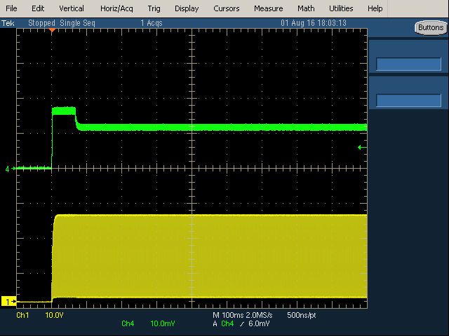
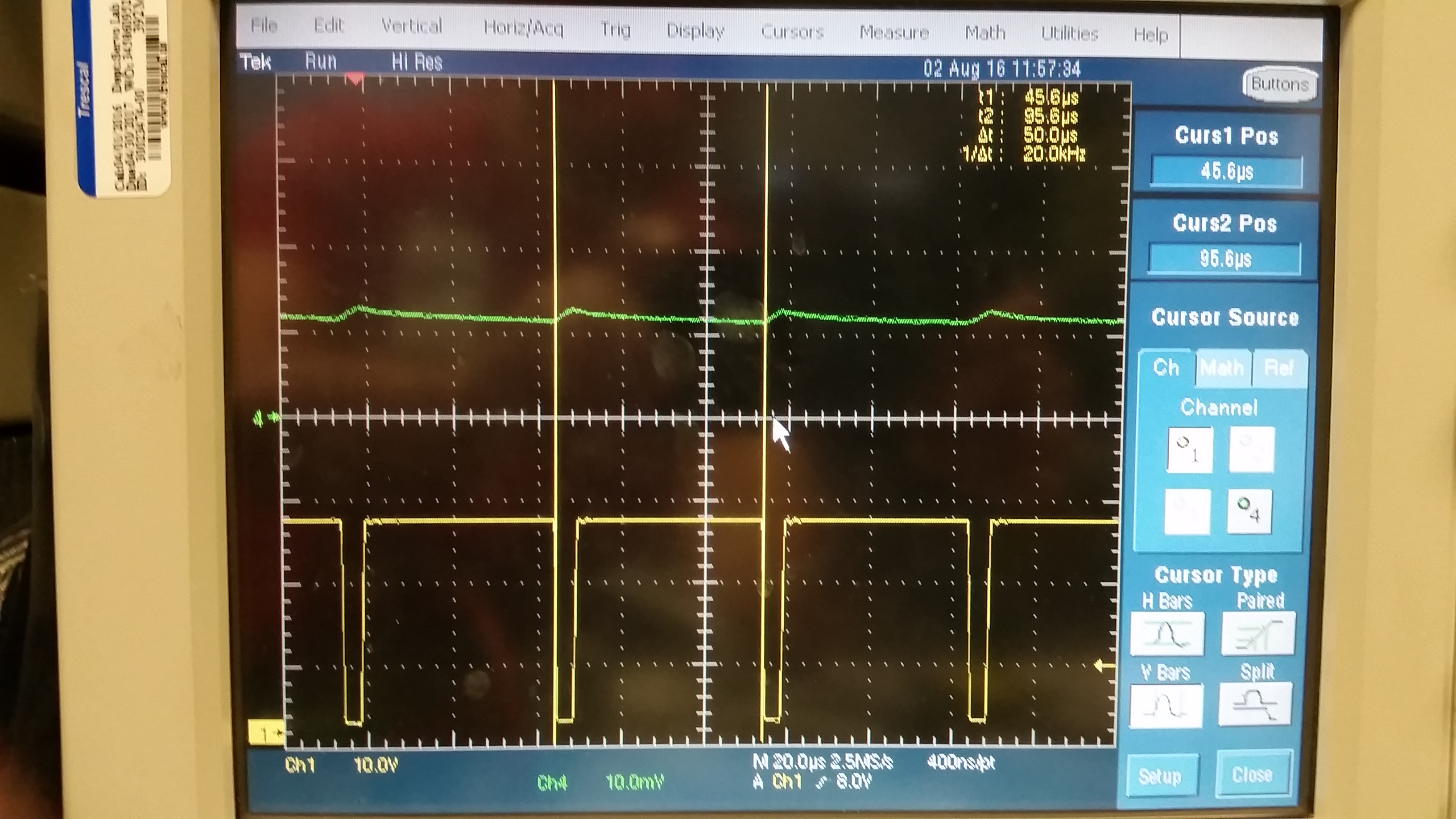
We first had a resitor of 47k on R3. That produced a good signal on PIN 7 OUT. it gave a Tkeep of about 170mS. I measured with an scoop on VIN and on OUT of the chip. after 170mS we see VOUT is PWM

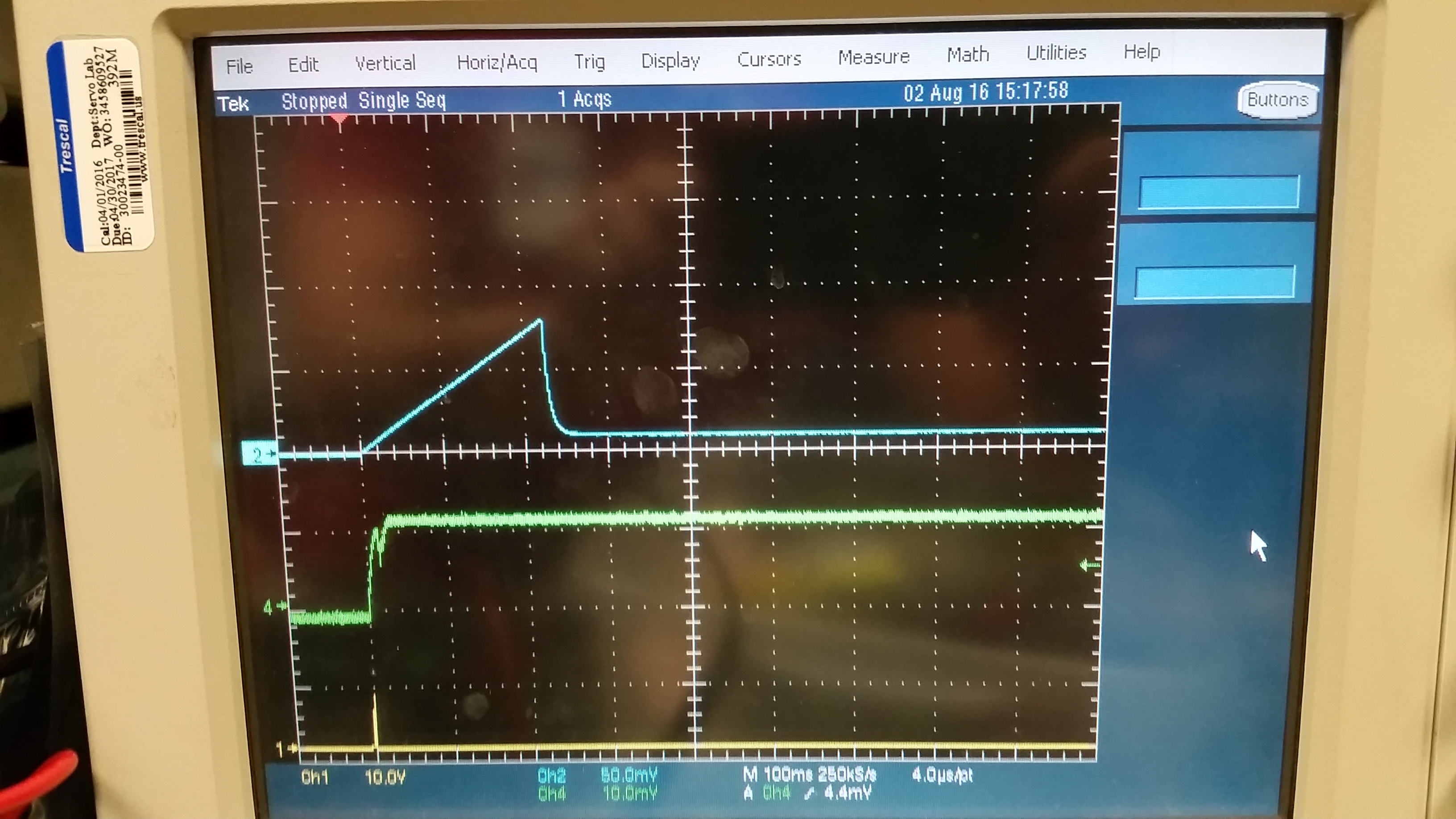
Second we changed only R3 to 68K. this gave us a tkeep of about 2 ms. When we look in the datasheet  on page 8 formula 1 we see only that tkeep is dependent on Ckeep.

  • Hi Marcel,

    Our experts have been notified and should reply soon.
  • Marcel,

    Thank you for posting about this. We are working to recharacterize this device and update the data sheet. In the meantime, please use a resistor greater than 160k on the OSC pin.

  • Dear mr Lockridge

    When we use a resitor of 160k we get a frequency of around 12 to 15Khz. C6 has a value of 2u20. I see that i have forgotten to give this value.
    So I suppose the formula to calculate the frequency is not correct.

    Marcel
  • When we use a resistor of 200k we get a frequency of about 10.5Khz. We wanted to get the freqency out of the hearing range to above 20kHz
  • When we use a 120k resistor we get a frequency of 18-22kHz and a tkeep of 180ms. When we use a 100k resistor we get a non stable frequency of 28kHz and a tkeep of 2ms. 68k gives freq of 60kHZ and tkeep 2ms. 200k gives freq of 10.5 kHZ and tkeep 170ms.
  • When we use no resistor it does not work. (What we expected) With 0R the frequency is 21kHz and the tkeep is 158ms.
  • How is the inductance of the coil related in the formula's. We measured the inductance of several coils they are in the range of 364mH to 403 mH.
    Measured with an LCR meter TENMA 72-6634 as indication. We see only one mention of 1H in the datasheet no minimum or maximum value. So we think, the value of the solenoid (mH) is the problem. Is there a formula to take that into account? We also tried 2H which doesn't oscillate. We also tried a 0.5H coil which functioned almost ok.
  • Is there a replacement for the DRV120 that can drive smaller inductions?
  • Marcel,

    The inductance on the out pin should not be an issue here, but the other information you posted is interesting. Would you please send me the following information so I can better understand your test setup and results?

    • Schematic of test board
    • Resistance of solenoid coil
    • Supply voltage used
    • Is this a solenoid or a relay? Please send me the part number and link to the datasheet.
    • You said that you had an LCR meter - would you please measure the actual capacitance of the 2u20 cap?

    Would you please send scope shots of following conditions:

    • 120k resistor showing 18-22kHz and tkeep of 180ms
    • 100k resistor w/ "non stable" frequency of 28kHz and a tkeep of 2ms. Would you explain what you mean by "non-stable frequency?"
    • 68k gives freq of 60kHZ and tkeep 2ms
    • 0R w/ frequency of 21kHz and the tkeep of 158ms

    In your scope shots, would you please include the following traces:

    • Current through coil
    • Voltage at OUT pin
    • Voltage at KEEP pin
    • Voltage of VIN

  • How can I send some files like pdf's and excel files and jpg, bmp to you?
  • Hi Marcel,

    Please select the "Use rich formatting" option on reply. Once selected the options to insert media (jpg and png files) or attach files will be available.

  • Marcel,

    Thank you for sending me this detailed information. I plan to go to the lab tomorrow morning to do some tests with the DRV120.

    James

  • Marcel,

    The functionality of the DRV120 should not be affected by the inductance of the coil. I did some tests in the lab today, and did not see any issues with the output waveform. I used the DRV120EVM for testing and supplied it with 24 V from a bench power supply. For these tests, I used ~200 Ohms for the OSC resistor (adjusted with potentiometer). The device on the EVM board is the DRV120A (14-pin version), so I was able to adjust the peak and hold values. I found that if I increased the HOLD current, that the audible ringing of my relay would get quieter, so that is one thing you can try to reduce the ringing, but it will mean you need to use the 14-pin version instead of the 8-pin.

    This scope shot is from a relay w/ a coil measured at 600mH and 660 Ohms. The current profile is in green (20 mA/div), and the OUT pin voltage is purple.

    This scope shot is from a solenoid measured at 20 mH and 11 Ohms. The current profile is in green (50 mA/div), and the OUT pin voltage is purple.

  • Marcel,

    Can you please take another scope shot for me?

    - Use a resistor greater than 160 kOhm for ROSC
    - Supply your board with some voltage between 12-24 V
    - Take the scope-shot with a time scale of 100-200 ms/div - I want to see the full current profile going from peak to hold
    - Show traces for the current through the solenoid and the voltage at the out pin
  • Can you tell me what is the frequency is on the output when in hold  current.

  • Marcel,

    I took a couple more scope shots, zooming into the hold section. The frequency looks like its ~21-25 kHz.

    20 mH

    600 mH

  • I have a question. In the application we use , we have a room/space shortage. This is why we have choosen is not chosen for an 8 pins tssop. Why choose on the 8 pins for an I-keep and not I-hold? Normally when a relay / Solenoid is switched only during a short time a high current runs. For a possible long time the relay is running on hold current. By reducing this hold current you can greatly reduce power consumption.
    Your answer will be use a 14 pins but we don't have the room.
  • With the I-keep in prevouis. I mean I-Peak. So why not change the Peak-limit (pin 2) to a I-Hold current limit pin ?
  • Marcel,

    That is a good question. We appreciate your feedback here so we can get an idea of what our customers want in new products.

    Today I received some samples of the 8-pin device. I will try and replicate your issue in my lab, but it may take a few days to send you results. Have you been able to resolve your issue yet?

    If you send me a private message with the following information, it will help me make the case to assign higher priority to my investigation on this issue.

    - Name of company
    - Production date
    - End equipment
    - # of DRV120 in each system
    - Estimated sales volume/year
    - Email and phone
  • Hello James

    When you try this new 8 pins device mount R3 with a 68k resistor and solder a 1N00 ceramic capacitor on top of it.
    Leave C6 to 2u20 and C7 stays 4U70.

    Please let me know your results :-)
    I don't have a 14 pins device but should also work as the 8 pins version I think.

    Now the second problem I am testing is heating of the coil.

    Marcel
  • Hello James

    I ordered some samples at ti.com of the 14 pins device. I hope I recieve them soon.

    Question
    What is the lowest value of hold current you have measured using the 14 pins device.

    Marcel
  • Marcel,

    I have gotten the hold current very close to 0 mA with the 14-pin device. According to the datasheet, the typical minimum duty cycle is 9%, so that will determine the minimum current based on your supply and solenoid parameters.

    I plan to do further evaluation on the 8-pin device this week and let you know my results.

  • Marcel,

    I've done some further investigation on this issue. Inside the 8-pin device, HOLD is left floating. I took the potentiometers off of the DRV120EVM and used the 14-pin device like the 8-pin device by floating the HOLD pin. I then grounded the OSC and PEAK pins, so they were set to default settings. The interesting thing I found was that a low-resistance, low-inductance coil performed as expected, but the high-resistance, high-inductance coil (one that is similar to yours) had issues. My scope shots are below.

    From what I observed on the bench, I believe that if you use the 14-pin device and do NOT float the hold pin, you should get reliable performance.

    Thank you for bringing this issue to our attention. We will need time to do further investigation here and improve our products and documentation.

    Let me know if you have any other questions.

    20-mH, 11-Ohm coil

    600-mH, 660-Ohm coil

  • Hello James,

    Can you tell me what the switching frequency is during the peak current and during the hold current at the 20mH 11 Ohm coil?

    Can you tell me what the switching frequency is  during the hold current at the 600mH 660 Ohm coil? 

    The frequency does not show on the image.

    If I take a look at page 9 of the datasheet I think the hold pin is connected to gnd in the 8 pins device??? Also on page 5 there is a line "CURRENT CONTROLLER, INTERNAL SETTINGS" showing 

    IPEAK Peak current PEAK = GND 160 200 240 mA
    IHOLD Hold current HOLD = GND 40 50 60 mA

    So if you gnd the peak pin you get a 20kHz. You also recommended me to use a resistor greater that 160k?

    Did you also connect a 68k and a 1n in parallel to the osc pin liked i suggested?

    What has the big influance the resistance or the inductance of the coil?

    Are there  "big" differances between the 8 pin and 14 pin device?

    We also already have about a 1000 pieces of the 8 pins chips already here on-site.

    Is there a way to return them and exchange them for 14 pins devices. Who do I have to contact if this is possible?

    With kind regards,

    Marcel

  • Marcel,

    Let me answer your first two questions in this post, then I will respond to the others.

    With the OSC pin to ground, the frequency is 20 kHz. I measure that for both coils.

    20 mH

    PEAK

    HOLD

    600 mH

    HOLD (Ipeak is V/R because resistance is large and regulation is not needed)

  • Marcel,

    I've seen the bond wire diagram, and HOLD is not connected to ground on the 8-pin device. We need to correct the datasheet here. The parameters on page 9 should be correct when you ground the PEAK and HOLD pins on the 14-pin device.

    My guess is that both L and R play a part due to the L/R time constant and its impact on PWM signals. However, the part will not PWM at all if V/R is lower than the programmed current thresholds.

    Any resistance should be good for the PEAK and HOLD pins. only OSC needs to be grounded or greater than 160 kOhm,

    Only difference between 8 pin and 14 pin is the number of pins. both use the same die.
  • Marcel,

    This afternoon I was able to do some bench testing with the 8-pin device. For me it  worked properly with the 600mH coil. This result was unexpected compared with my results from the 14-pin device where I floated the HOLD pin. However, it is good to know that at least for this test, the 8-pin version is working correctly.

    The scope shots below have the following setup: blue = Vkeep, green = Isolenoid (50mA/10mV), yellow = OUT. I replicated your schematic on a breadboard for these tests.

    Rosc = 68k - here the device is not in the operating region because the Rosc is too low. We can tell that the device does not go into the PEAK state because Vkeep isn't increasing. We can't see the PEAK state in this waveform because V/R is lower than the threshold for the sense current.

    OSC pin connected directly to ground - In our testing we found that this is a stable operating state. Here Ckeep is charging correctly.

    Rosc = 160k - This is also a stable setting

  • Hallo James

    Did you also solder the 1N Farad capacitor onto the 68k and then connect it to the osc pin and the other end of those 2 to gnd?

  • I did not connect a capacitor there. My test setup was also on a breadboard. Have you seen improvements in performance when you do that?

    Also, I sent an email to the address you provided me in your private message. Let's move our discussion over to email.