


Hi,
My customer is using DRV8881PEVM and customer motor.
Then, he has a issue.
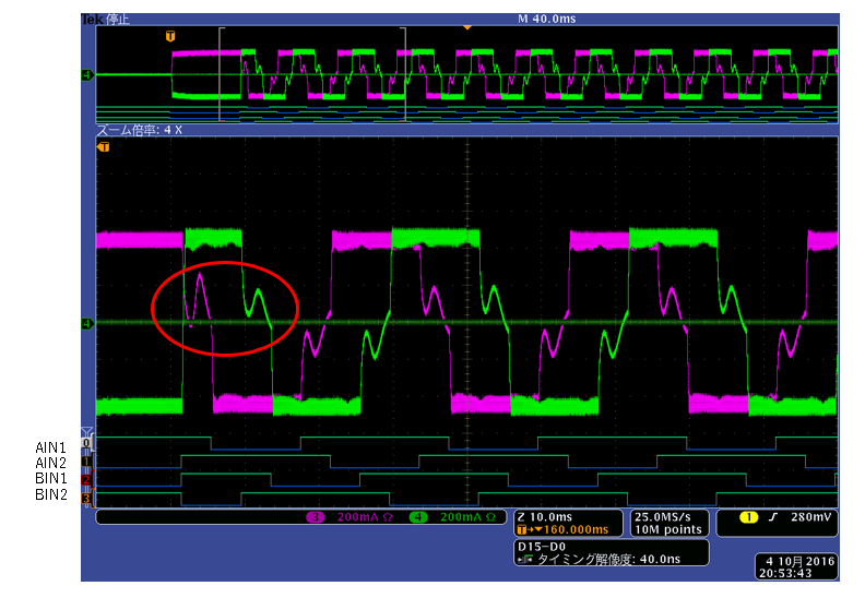
Please see the below picture.
This is current waveform.
Motor operates at 1-2 phase.
Do you know the reason of red circle of this picture?

Best regards,
Shimizu
Hi,
My customer is using DRV8881PEVM and customer motor.
Then, he has a issue.
Please see the below picture.
This is current waveform.
Motor operates at 1-2 phase.
Do you know the reason of red circle of this picture?
Best regards,
Shimizu
