This thread has been locked.

If you have a related question, please click the "Ask a related question" button in the top right corner. The newly created question will be automatically linked to this question.

DRV8833 Outputs Incorrectly Connected?

Other Parts Discussed in Thread: DRV8833

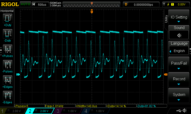
Hello, I am using a product that has DRV8833's installed (I did not design the product), with AOUT and BOUT ganged to double the output current and drive one motor from one DRV8833.  I have been noticing unusual output waveforms from the channels, and when I took the device apart, I see that AOUT1 and AOUT2 are connected, and BOUT1 and BOUT2 are connected-- this is not the way ganging is shown in the datasheet (AOUT1 and BOUT1 are connected, and AOUT2 and BOUT2 are connected).

Could the way this manufacturer designed the product (incorrectly ganging the outputs) be causing the odd waveforms?

Thanks!

--Rob

  • Hi Rob,

    It is possible the connections are causing the odd waveform.

    Can you describe the unusual output waveforms or provide a scope capture?
    How are the inputs connected?
    How is the motor?
    What is the VM voltage and sense resistor value?
  • Hi Rick, thanks for your reply.  I'm not the best at using the scope, but here's what I captured:

    I would have expected to see nice, clean waveforms, but after having read elsewhere on this forum, I wonder if the OCP trigger is being hit.  The product's design does not use current sense resistors (just connected the sense pins to ground).  Input voltage is 7.2v DC, and the inputs are connected to a Bluetooth module (this controls the DRV8833).  Several different motors can be connected to the outputs, and the capture above shows the waveform when the largest motor is connected.  Here's a link to more specs on that motor:  www.lego.com/.../8882-actions-7bf92962d5d746a8a48fc50fa1e561cc.

    I hope this information is helpful.  Let me know what you think, thanks!

    --Rob

  • Hi Rob,

    What signal is being captured on the image provided?
    This does not appear to be an overcurrent event assuming this is a single output shown, because the overcurrent protection period is ~1.4ms.

    Can you provide a basic schematic, and the inputs waveforms also?
  • Hi Rick, sorry about the unclear capture-- as I said, I'm new to the scope. This is one of the output lines (AOUT1 and BOUT1 tied together) driving the motor in one direction. The curves should be standard PWM curves, but there's a lot of noise in the middle of the waveform where it shouldn't have noise. This makes me think that AOUT1 and BOUT1 are really working against each other when trying to drive the motor forward-- I can see that AOUT1 and AOUT2 would drive it cleanly, but it seems like AOUT1 and BOUT1 must always be fighting each other, since you can't have an "A" output and a "B" output of an H-bridge working together. Is this theoretically accurate?

    Since I didn't design this product, I don't have a schematic. The board is very small, so I would need to do a bit more digging to trace the input signals. What I was hoping for was a theoretical answer about whether AOUT1 and BOUT1 should ever be tied together in a design. Why would you ever recommend this?
  • Hi Rob,

    To double the current AOUT1/BOUT1 and AOUT2/BOUT2 should be connected together. This allows xIN1 and xIN2 to control the outputs in parallel. The outputs propagation delays are matched to allow parallel operation.

    Connecting AOUT1 and AOUT2 together might work if the motor is being driven in one direction and the outputs are PWM'ed between low and coast.
  • Thanks Rick for the quick replies. The point about the outputs being PWM'd between low and coast is interesting. I ordered some current sense resistors to see if adding them to the PCB changes operation in any way. I'll also reach out to the manufacturer to see if they can explain the reason they decided to pair AOUT1 and AOUT2.

    Again, I appreciate the great responses!