This thread has been locked.

If you have a related question, please click the "Ask a related question" button in the top right corner. The newly created question will be automatically linked to this question.

BOOST-DRV8711: About cause of failure

Part Number: BOOST-DRV8711
Other Parts Discussed in Thread: DRV8711, , CSD88537ND

I evaluate DRV8711 using evaluation board BOOST-DRV8711 with +24V.
During that time, several boards broke.

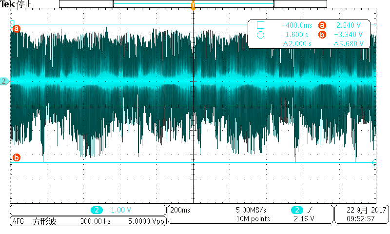
Cheking the cause of failure, there is large spike noise on feedback
voltage for AISENP.

Absolute maximum rating of ISENSEx pins voltage defined from -0.7V to
+0.7V.
But my evaluation status, this voltage is over 2V and under -3V.
  "please see attached pictures."

Does this spike noise cause of failure?
Does this input signal accept or not?

  • Hello user5122878,
    The isen pin is violating our abs max values and possibly damaging the device. Can you please provide the following values:
    What is the Risense value you are using?
    What is the TORQUE setting?
    What is your ISGAIN setting?
    Thank you.
  • Hello Mr.Riveros
    Thank you so much to reply quickly.

    Risense value is 0.05Ω (same as Evaluate board)
    TORQUE setting is 20h(32b)
    ISGAIN setting is 5 (same as default setting)

    Perhaps signal waveform is depend on characteristic of motor.
    I write relevant parameters below.

    VM :24V
    Qg :14nC   (using CSD88537ND)
    RDS :12.5mΩ (using CSD88537ND)
    RL :5.4Ω/phase
    LL :2.9mH/phase
    CL :unknown
    θ  :1.8/step
    IL  :1.0A/phase
    Rsense:0.05Ω
    nm :64step
    v :1.4rpm
    IFS :1.4A
    RT :15ns
    fPWM :77.5kHz

    For your reference, I also write other configuration below.

    TORQUE REGISTER: 17h,20h (SMPLTH 1000us, TORQUE 32)
    OFF REGISTER : 20h,10h (use internal indexer, TOFF 8us)
    BLANK REGISTER : 31h,A0h (Enable adaptive blanking time, TBLANK 3.20us)
    DECAY REGISTER : 45h,10h (DECMOD auto mixed decay, TDECAY 8us)

    Best regards
    Kei.Sugimoto
  • Hello Mr.Riveros.

    I tried to insert an external filter on the current sense resistor.

    R = 500Ω, C = 100pF

    Then,spike noise reduced compare with before external filter.
    But noise level is still exceeding from -0.7V to +0.7V.

    On another question's answer,
    There was reply
    "small spikes above +/-.7V (Transients of ±1V for less than 25ns) are acceptable."

    e2e.ti.com/.../1570579

    How about the spike level of attached picture? Is it acceptable or not?

    Best regards
    Kei.Sugimoto

  • Hello Sugimoto-san,
    I apologize for the delayed response, could you please send a zoomed capture of the sense pin? ~100us division should be fine. Also, please take a differential measurement so extra noise is minimized. Thank you.
  • Hello Mr.Riveros.

    Thank you so much to remember.

    I captured the signal of the sense pin.

    Sense resistor is 0.05Ω.

    And inserted external filter. ( R = 500Ω, C = 100pF )

    I only have one set of diffrential probe.

    So, I used to take the signal of after filter.(ch3)

    Your request was 100us division capture.

    But this division's capture can't see the width of spike.

    So, I also attached 100ns division's one.

    How about that.

    Kei.Sugimoto

  • Hi Sugimoto-san,

    Thank you for the captures provided. It looks to me that spikes now are okay and should not be the cause of failure if failure still exist. Do you still see the issue even with adding the external filter?