This thread has been locked.

If you have a related question, please click the "Ask a related question" button in the top right corner. The newly created question will be automatically linked to this question.

DRV8305: Inconsistent Dead-Time

Part Number: DRV8305
Other Parts Discussed in Thread: DRV3245Q-Q1

I'm struggling to understand what is going with the dead time in my circuit.  I understand that the DRV8305 tdrive system automatically ensures that a switch is turned off prior to turning on the opposite transistor.  This is a great feature in concept; however I am concerned that the dead-time that it inserts is not consistent, and varies by 40nS between switching cycles.  

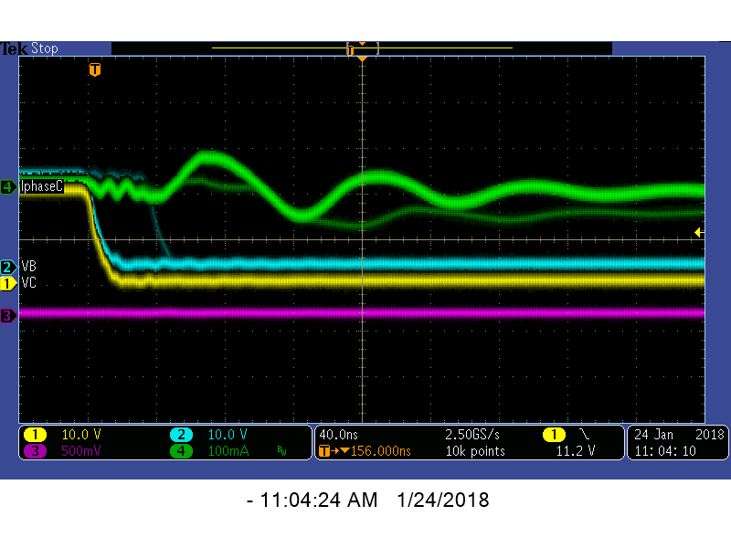
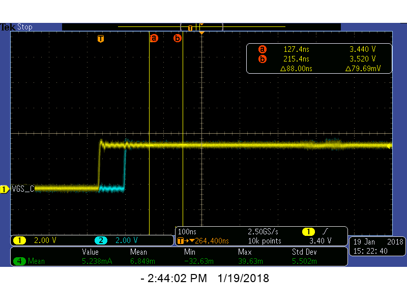
I've got my processor outputting constant pwm, and when I look at the low side there is a consistent relationship between the gate commands (see second scope trace),  however when I look at the actual gate commands coming out of the DRV8305, I see inconsistency.  Below is a scope shot of that; Yellow trace is phase B lower switch gate.  Blue trace is phase C lower switch gate.  Current is flowing, but small, pwms are in a fixed state.  You can see that the blue trace is going high either 40 or 80ns after the yellow trace (the trigger)

This plot below shows the same signals at the input to the chip - no variation visible.

I'm running a very low inductance motor, so when the motor is stopped, as it is in this test, the duty cycles are small.  The variation that is being created by the dead-time inconsistency has a large impact on current, and causes instability.  I'd like to make it go away.  Is there some way to turn off dead time on the DRV8305?  Then I will generate deterministic 100uS dead-time on my microcontroller.  If there is not way to turn it off, what steps can I take to stabilize this effect?

Thanks

  • Hi Geoffrey,

    I have a few follow-up questions to help me understand your setup better.

    • Is the variable dead time you observe causing a performance issue in your system that you want to fix?
    • Are you using the device in 1-, 3-, or 6 PWM mode?
    • What deadtime setting did you choose?

  • Thanks James - I'm hoping to get some ideas to work on over the weekend, so any reply will be helpful.

    * Variable dead-time is causing a performance and noise issue - the PWM frequency is 80KHz, and the line-line on time is only about 300nS when motor is not moving; 40ns change in dead time is very significant

    * We are using device in 6PWM mode (the first one)

    * we chose 35nS deadtime - and I've tried with with and without another 100nS from the micro, but I get the same behavior.  To me it seems like it could be time-quantization of the chip deciding that the transistor is off, I will try selecting a different deadtime and see if the variablity changes.

    Geoff

  • Hello James,

    I am working with Geoff on this issue and wanted to share the following scope capture. In this capture, the trigger is on the rising edge of a low side gate and I am zoomed in on the falling edge with a 1sec persist on the display. As you can see there are five distinct bands of fall times with intensity indicating a sort of normal distribution around the middle time. Of note is that the bands are all separated by the 35nsec minimum deadtime that we have programmed into the driver. This seems like more than a coincidence. One of our working theories is that the sensing for internal handshaking is varying somehow from cycle to cycle and therefore the deadtime addition is starting at a different point. However, we don't understand how this could happen with fixed source/sink currents to the gates.

    BTW - I should also mention that these tests are being done with the rotor locked so that there is no sequencing on the uC side - same PWM sequence is being issues continually to the driver.

    Thanks, Jamie

  • Geoff and Jamie,

    Jamie brings up an good point about the handshaking varying from cycle to cycle. Can you take a scope shot showing all the gate signals that switch during this particular transition (high-side and low-side)? This will help us see the whole picture. I expect that if you switch a FET on a bridge that is not energized, the FET will switch immediately. If you switch both FETs on a bridge that already is energized, then the TDRIVE feature will activate to add dead time.

    Do you only experience issues during this locked rotor test? Is the locked-rotor condition a normal operating condition in your application?
  • James - I don't have a scope, or diff probes needed to capture the whole picture all at once.  But I will attempt to do each leg separately, using waveform math.  

    Jamie mis-spoke, we are not doing the test exactly locked rotor, we actually have scaled way back chasing a position hold stability problem.  Currently I have only two of the three phase connected on my motor, and in software I have forced all current feedback to zero, as well as encoder feedback.  This results in phase A being 50% duty cycle, and phased B and C being complementary; we can even stop the code and keep the bridge running to ensure that there are no pwm changes.  We still see the variation in this case.  Jamie's scope shot is the gate signal falling edge whilst triggering on the rising edge, it is taken on a single energized phase with current flowing in continuous conduction mode.

    Can you provide any other feedback while you are waiting for those big picture scope shot(s)?  We are really stuck here, that jitter in pulse width is causing problems.   Is there some way to disable the dead-time in the DRV8305 so we can use just the microcontroller's timing, which is much more stable?

  • Geoff,

    Thanks for the additional information. Don't take any scope shots right now. However, can you please send me a timing diagram of your PWM inputs that you are trying to use for this holding sequence?
  • I don't have the board in working order right now, but the gates out of the microcontroller are like this - no dead time added.


    Phase AH (50% duty)   ________|^^^^^^^^^|_________|^^^^^^^^^|

    Phase AL (50% duty)   ^^^^^^^^|_________|^^^^^^^^^|_________|

    Phase BH (52% duty)  ________|^^^^^^^^^^^|_______|^^^^^^^^^^^|_

    Phase BL (48% duty)  ^^^^^^^^|___________|^^^^^^^|___________|^

    Phase CH (48% duty)  __________|^^^^^^^|___________|^^^^^^^|___

    Phase CL (52% duty)  ^^^^^^^^^^|_______|^^^^^^^^^^^|_______|^^^


  • James, any words of wisdom for us?  Do you need a better diagram?

  • Hi Geoff,

    Thank you for the PWM signals.

    I just spoke to a designer on my team, and he believes that the reason for the jitter is due to the spread spectrum clock in our device that synchronizes with the input signal to provide the signal for the gate drivers. I think this is similar to a hypothesis you had. Our design team is looking closer at the clock design, and seeing if we can give you a way to shut off the synchronizing and drive the outputs directly.

    The designer also thought that this jitter should not affect acoustic performance of your motor. The time scale of the spread-spectrum clock is significantly smaller than your PWM signal and acoustic frequencies. This gives me a couple more thoughts of things you can look at in your overall system. Let me know your thoughts on these suggestions.

    1) Check your positional feedback signals. If I understand your setup correctly, you have a BLDC motor that is holding the rotor at a fixed position, and you have an encoder providing feedback to your MCU.

    • Is the encoder precise enough for the position you are trying to maintain? I'm thinking that if you try to maintain the rotor at a position that lies between two encoder values, you may see some oscillation as the control system tries to correct it.
    • Is there noise somewhere in your feedback path? Using a digital signal from an encoder should be pretty clean, but a noisy environment might cause bits to flip.
    • Are there delays in your feedback path? If the delay in interpreting the encoder value is significant, then the controller may try to regulate the motor position to the wrong location. Delays might be caused by reading an encoder with serial communication, by processing the encoder feedback, or by the cycles needed to adjust the control loop.

    2) Check the phase currents of the motor. Motor torque is a function of motor currents, and torque is what ultimately causes motion. If you have some kind of vibration in the currents, this will cause vibrations/acoustic noise in your motor.

    Because you are seeing vibration, you may likely some kind of affect in the motor currents. However, the way the motor currents act may tell you if you are somehow losing regulation to the jitter, the control loop, or some other reason.

  • Thanks James - I'm interested in learning more about the spread spectrum clock - what is the frequency range and how does it transition between frequencies?  Is it brought external anywhere that I can see it?

    Your comment about encoder feedback is appropriate, however in the interest of eliminating possible sources, we have already modified out code to disable the feeback; also remember that this issue happens even when we stop the code at a breakpoint and keep the pwms running.

    To give you an idea of the effect I've made a zoomed in view of phase B and C switching outputs when the duty cycle is set to 50%, and this is precisely what is coming from the micro, you can see that phase B occasionally shuts off 35ns after phase A, creating a differential voltage across the motor winding.  This is caused by changes in the switching waveform introduced by the DRV8305.  The result is 50mA of undesired current flow in the motor.  Later, I'll show another plot with current flow.

    The scope shot below shows the effect when running with 3A (about 25% of inverter rating) - you see on top the large scale effect, as well as a zoomed in view of the switch variation (triggering on Phase C, so it shows on phase B) As is clearly visible, there is jitter on Phase B, and it results in about 300mA  of current variation.   Again - no control loops or feedback is involved; the code is not even running.

    Since you are probably wondering what the gate signals look like - the scope shot below shows the low side gate voltages - exhibiting the same jitter.

    If we can't disable the source of this jitter, I'd love some suggestions to help minimize the effect of it on my control loop.  I've already reduced switching frequency from 80KHz to 40KHz, and that has helped, 

  • Hi Geoff,

    Sometimes there is a way to look at the clock or bypass the synchronizer. However, many times this is through a complicated test mode or with one-time programmable bits that are only used during production testing. I will follow up with the designer to see if we can give you that option.

    I see a couple effects on the current in your waveforms, particularly the second scope shot. 1) The persistence shows that the current sometimes tracks higher than other times. That may be due to jitter. 2) There is a clear ripple at your switching frequency. This appears to be due to the ~250 ns delay between the VC transition and the VB transition in the scope shot. To me, item 2 is the cause of your acoustic noise issue. Can you help me understand better why you think the jitter causes the acoustic noise?

    Here are a few more debugging thoughts/questions.

    1. In your application, can you hold the rotor position at a location that requires PWM on only two phases instead of all three? if you try this, does the noise performance improve?
    2. Just for testing purpose, can you use a larger-inductance motor to see if it has similar issues?
    3. Are you using current sense feedback? Instead of using a fixed PWM duty cycle for this condition, can you use current feedback to regulate the currents in the rotors and achieve the rotor position you want?

    Since your test setup is a simple PWM without any control techniques, can you send me a software example I could use or recreate? I use Code Composer Studio with MSP430 and C2000, so if you're able to simplify your software condition to provide these PWM signals and allow me to change the frequency, I can create this on the bench much faster.

  • Thanks James - The ripple is expected and intentional, this is how pwm works, when there is a voltage potential due to opposing legs being active, current rises, when the opposing legs are at the same potential, the inductance keep current flowing, and there is a small reduction in current. By averaging this over time, you get control of the current in the inductor. The delay was represented in my pwm sketch.

    Regarding question 1. I am currently not using any feedback from the encoder, and have chosen 0 degrees as my input, so it indeed demands no current from phase A.

    Regarding 2. I see the same jitter, but as you would expect, the current ripple, and the variation in average is reduced as a result.

    Regarding 3. Currently I am not looking at the current feedback. I started with that and found that the controller was not able to manage the current well due to that jitter. I'm going to move back towards that, as it sounds like we are going to have to live with the jitter until we can design in a different driver chip.

    I don't have the ability to give you any code, but it should be very easy to see this with any code that you already have that makes pwm. Simply trigger on the rising edge of the gate signal, and look at the falling edge, you will see this 35nS jitter. Please try it and let me know that you can see the same thing.

    Thanks,
    Geoff
  • Hi Geoff,

    I provided your feedback on the DRV8305 feature set to my systems engineer. He had a couple suggestions of things you can try.

    • We have the DRV3245Q-Q1 pre-release information on the web. It should be a pin-for-pin replacement of the DRV8305, and should have an asynchronous mode where you can control the FETs directly to add your own dead time. I think you can request samples of the device.
    • You can also choose devices from our MOSFET and IGBT Gate Driver portfolio. They don't have the protection features of the DRV8xxx devices, but they give you more independence for timing.

  • James - thanks for the recommendation, it's interesting and nice that it's the same package. Unfortunately we are switching at 40KHz, and the datasheet says that the DRV3245Q only supports 20KHz max, how would it behave if we push the switching frequency limits?

    Also, can you provide any information about the spread-spectrum clocking that is inside the DRV8305? I think that would reveal the true nature of the problem I'm seeing.
  • Geoff,

    The 20 kHz number comes from a charge pump limit based on FET size. However, the device will support switching up to 40 kHz and higher.

    The clock inside the DRV8305 is 25 MHz. When I showed your waveforms to our designers, they said that the jitter looked like it could have come from variation of triggering across one clock cycle.
  • OK - that makes sense; 40nS. I would recommend adding that to the datasheet. I will ask our local sales office to help with samples.

    Geoff
  • One follow up question; does the DRV3245Q have the same clock, and would it have the same issue? The term "asynchronous" probably implies that it has no clock and therefore no issue, but want to check.

    Geoff
  • Geoffrey,

    The DRV3245Q still has an internal digital core and oscillator but there is not internal feedback dead-time control for the drivers. The digital core is to manage fault diagnostics and configuration settings. The PWM signals are asynchronously sent to the analog gate drivers to combat the problem you are describing.

    Tradeoff for this is that the driver cannot manage dead-time itself it needs to come from external controller.

    Note that the DRV3245 while improved in this aspect compared to DRV8305, will still not match a high performance half-bridge driver such as the UCC designed for high frequency applications.

  • Thanks Nick - I'm not familiar with UCC, can you elaborate so I can check it out?

  • Geoff,

    The UCC parts are H-bridge drivers used in power supply design, but they should work for motor drive applications. They are part of our MOSFET and IGBT Gate Driver portfolio.

  • Hi Geoff,

    I know you may be moving onto another driver chip solution, but I had one more thought for your current system. Did you try changing the VM voltage? I'm thinking that with a lower voltage on the bridge you could use longer duty cycles, maybe increase your switching frequency again, and have better acoustic performance. Even if you left your frequency the same, hopefully the longer duty cycles would reduce any error the jitter causes for your current regulation.

    If you tried this, or if you get a chance to try this, please let me know the result.
  • It's a good thought.  I've tried running from bench power at half voltage, and the problem does get better, but not by enough.   Also, we have a pre-defined battery in the system that we cannot change, it ranges in voltage from 18-31 volts.  Another option would be to add series inductance to the motor, also for the effect of increasing the duty cycles.    In either case, the duty cycle gets longer, but the jitter still remains, and therefore there is some undesired voltage noise applied to the motor.  To give you and idea of the sound, I've attached an audio file, recorded with my phone microphone next to the motor.

  • Geoff,

    Thanks for sharing these results. I know redesigning your board with a new device is a pain, but I hope you have success with one of the other solutions Nick and I mentioned.