This thread has been locked.

If you have a related question, please click the "Ask a related question" button in the top right corner. The newly created question will be automatically linked to this question.

DRV8323: Independent control 3 half bridge

Guru 16770 points
Part Number: DRV8323

Hi

I suppose to use function of smart gate driver for following usecase.

Could you please answer the questions?

1.

Is it possible to configure following circuit using DRV8323?

- Each half bridge is controlled by MCU independently.
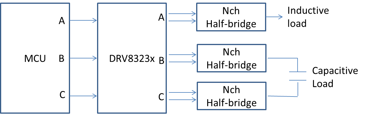
2.

Is it possible to use capacitive loads like electrode?

3.

Is it possible for each half bridge circuits to use supply voltage different with VM voltage?

BestRegards

  • Hello na na78,

    1) Yes, each half bridge can be controlled independently with the DRV8323.

    2) The only issue I see here would be with our overcurrent protection (VDS_OCP) disabling the device due to the large inrush current. However, depending on your application requirements, you could program the OCP retry time (DRV8323S) or disable the VDS threshold (DRV8323H) to accommodate those large currents. Other workarounds may exist as well, such as using a resistor in series to limit the inrush current.

    3) I think this should be possible. I recommend connecting VM and VDRAIN to the supply with the highest voltage if you want to do this. The only other concern I would have is with the OCP_VDS sensing. It will only work properly for the load that is connected to VDRAIN. What voltages are you considering for each of the half bridges? I'll ask our design team if this is possible.
  • Hi James

    Thank you for your reply.

    I want to correct the information about Nch FET configuration.

    It would be configured one is half bridge and one is full bridge which is configured by lower two half bridge on the figure.
    Regarding to half bridge, 16V will be applied.
    Regarding to full bridge 4V to 14 V would be applied.

    Could you give us further view?

    BestRegards
  • na na78,

    I received feedback from our designer.

    - The DRV8323 must have VM and VDRAIN on the 16-V supply.

    - There is some risk for the internal protection circuitry. Figure 26 in the datasheet shows a zener diode on the high side gate driver. The breakdown voltage is around 16 V. If the high-side of the 4-V bridge is on, this puts 4-V on the SHx pin/Zener diode anode. The other side of the Zener is on the GHx pin, which will be at 26 V (16 V supply + 10 V charge pump). The 22 V across the Zener will cause extra current to flow through this path. I would try to reduce the voltage difference as much as possible. To stay below the Zener breakdown voltage, I recommend having the supply of the inductive load to be no less than 10 V.

    Can you have all bridges on the 16-V supply, but use PWM to regulate your voltage across the inductive load to the desired value? I think that solution would have fewer potential issues for the DRV8323.