This thread has been locked.

If you have a related question, please click the "Ask a related question" button in the top right corner. The newly created question will be automatically linked to this question.

AM335X: Ethernet on custom board

Hi,


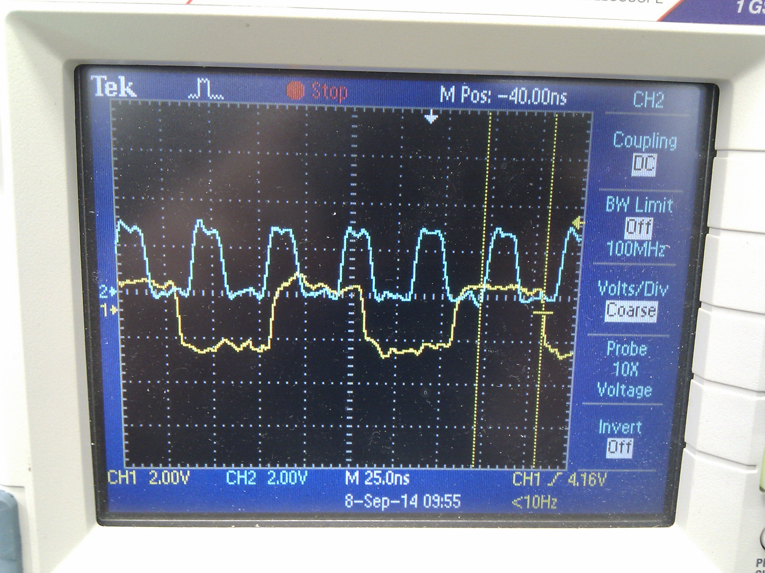
We are trying to bring up the ethernet on a custom board using the latest Sitara SDK. It looks like the phy is detected correctly and the network interface is available, however no packets are sent or received (which has been verified externally with wireshark).

The relevant parts of our DTS file are as follows:

In the pinmux section:

     cpsw_default: cpsw_default {
            pinctrl-single,pins = < 
                /* Slave 1 */
                0x114 (PIN_OUTPUT_PULLDOWN | MUX_MODE2) /* mii1_txen.mii1_txen */
                0x118 (PIN_INPUT_PULLUP | MUX_MODE2)    /* mii1_rxdv.mii1_rxdv */
                0x11c (PIN_OUTPUT_PULLDOWN | MUX_MODE2) /* mii1_txd3.mii1_txd3 */
                0x120 (PIN_OUTPUT_PULLDOWN | MUX_MODE2) /* mii1_txd2.mii1_txd2 */
                0x124 (PIN_OUTPUT_PULLDOWN | MUX_MODE2) /* mii1_txd1.mii1_txd1 */
                0x128 (PIN_OUTPUT_PULLDOWN | MUX_MODE2) /* mii1_txd0.mii1_txd0 */
                0x12c (PIN_INPUT_PULLUP | MUX_MODE2)    /* mii1_txclk.mii1_txclk */
                0x130 (PIN_INPUT_PULLUP | MUX_MODE2)    /* mii1_rxclk.mii1_rxclk */
                0x134 (PIN_INPUT_PULLUP | MUX_MODE2)    /* mii1_rxd3.mii1_rxd3 */
                0x138 (PIN_INPUT_PULLUP | MUX_MODE2)    /* mii1_rxd2.mii1_rxd2 */
                0x13c (PIN_INPUT_PULLUP | MUX_MODE2)    /* mii1_rxd1.mii1_rxd1 */
                0x140 (PIN_INPUT_PULLUP | MUX_MODE2)    /* mii1_rxd0.mii1_rxd0 */
            >;
        };

        cpsw_sleep: cpsw_sleep {
            pinctrl-single,pins = <
                /* Slave 1 reset value */
                0x114 (PIN_INPUT_PULLDOWN | MUX_MODE7)
                0x118 (PIN_INPUT_PULLDOWN | MUX_MODE7)
                0x11c (PIN_INPUT_PULLDOWN | MUX_MODE7)
                0x120 (PIN_INPUT_PULLDOWN | MUX_MODE7)
                0x124 (PIN_INPUT_PULLDOWN | MUX_MODE7)
                0x128 (PIN_INPUT_PULLDOWN | MUX_MODE7)
                0x12c (PIN_INPUT_PULLDOWN | MUX_MODE7)
                0x130 (PIN_INPUT_PULLDOWN | MUX_MODE7)
                0x134 (PIN_INPUT_PULLDOWN | MUX_MODE7)
                0x138 (PIN_INPUT_PULLDOWN | MUX_MODE7)
                0x13c (PIN_INPUT_PULLDOWN | MUX_MODE7)
                0x140 (PIN_INPUT_PULLDOWN | MUX_MODE7)
            >;
        };

        davinci_mdio_default: davinci_mdio_default {
            pinctrl-single,pins = <
                /* MDIO */
                0x148 (PIN_INPUT_PULLUP | SLEWCTRL_FAST | MUX_MODE0)    /* mdio_data.mdio_data */
                0x14c (PIN_OUTPUT_PULLUP | MUX_MODE0)           /* mdio_clk.mdio_clk */
            >;
        };

        davinci_mdio_sleep: davinci_mdio_sleep {
            pinctrl-single,pins = <
                /* MDIO reset value */
                0x148 (PIN_INPUT_PULLDOWN | MUX_MODE7)
                0x14c (PIN_INPUT_PULLDOWN | MUX_MODE7)
            >;
        };

In the main section at the bottom:

&mac {
    slaves = <1>;
    pinctrl-names = "default", "sleep";
    pinctrl-0 = <&cpsw_default>;
    pinctrl-1 = <&cpsw_sleep>;
};

&davinci_mdio {
    pinctrl-names = "default", "sleep";
    pinctrl-0 = <&davinci_mdio_default>;
    pinctrl-1 = <&davinci_mdio_sleep>;
};

&cpsw_emac0 {
    phy_id = <&davinci_mdio>, <4>;
    phy-mode = "rgmii-txid";
};

Are we missing anything?

An extract from the log output of our board is shown below:

[    1.883280] davinci_mdio 4a101000.mdio: davinci mdio revision 1.6
[    1.889775] davinci_mdio 4a101000.mdio: detected phy mask ffffffaf
[    1.898783] libphy: 4a101000.mdio: probed
[    1.903081] davinci_mdio 4a101000.mdio: phy[4]: device 4a101000.mdio:04, driver Atheros 8035 ethernet
[    1.912957] davinci_mdio 4a101000.mdio: phy[6]: device 4a101000.mdio:06, driver Atheros 8035 ethernet
[    1.924356] Detected MACID = 88:33:14:f6:a5:40
[    1.932584] omap_rtc 44e3e000.rtc: setting system clock to 2000-01-01 00:00:00 UTC (946684800)
[    1.952709] EXT4-fs (mmcblk0p2): INFO: recovery required on readonly filesystem
[    1.960614] EXT4-fs (mmcblk0p2): write access will be enabled during recovery
[    2.405128] EXT4-fs (mmcblk0p2): recovery complete
[    2.414889] EXT4-fs (mmcblk0p2): mounted filesystem with ordered data mode. Opts: (null)
[    2.423673] VFS: Mounted root (ext4 filesystem) readonly on device 179:2.
[    2.441941] devtmpfs: mounted
[    2.446572] Freeing unused kernel memory: 344K (c074b000 - c07a1000)
>[    3.257562] udevd[774]: starting version 182
[    4.332742] PM: CM3 Firmware Version = 0x186
[    8.777545] FAT-fs (mmcblk0p1): Volume was not properly unmounted. Some data may be corrupt. Please run fsck.
[    9.179152] cryptodev: driver 1.6 loaded.
[    9.344977] EXT4-fs (mmcblk0p2): re-mounted. Opts: data=ordered
[   10.898297] net eth0: initializing cpsw version 1.12 (0)
[   10.908485] net eth0: phy found : id is : 0x4dd072
[   10.930765] 8021q: adding VLAN 0 to HW filter on device eth0
[   13.904110] libphy: 4a101000.mdio:04 - Link is Up - 100/Full
[   23.663038] couldn't find an available UDC

As you can see the phy is detected on MDIO address 4 and the link is detected (the second phy on addr 6 is currently unused).

Any help appreciated, we are at a loss!

Thanks in advance,

Rob Connolly

  • Hi Rob,

    I will ask the factory team to look at this.

  • What does ifconfig show for the ethernet port? Please attach the part of the boot log showing where the DHCP process is happening. just to confirm this is the 7.0 SDK?

    Also why is slaves being set to 1 from original value of  2 in the MAC node definition?

  • Do you see any activity on the interface itself?

    Any activity on RX_CLK and GTX_CLK?

    If yes to above questions, have you enabled internal delay for both RX_CLK and GTX_CLK on the PHY (or did you account for the required CLK delays (1.8ns +/- 300ps) on the PCB itself)? 

  • Yes, this is definitely the 7.0 SDK.

    I had copied the slaves value from the DTS for the beaglebone, however setting to 2 and defining another cpsw_emac section for the other phy doesn't help.

    Ifconfig shows:

    eth0      Link encap:Ethernet  HWaddr 88:33:14:F6:A5:40  
                  UP BROADCAST RUNNING MULTICAST  MTU:1500  Metric:1
                  RX packets:0 errors:0 dropped:0 overruns:0 frame:0
                  TX packets:5 errors:0 dropped:0 overruns:0 carrier:0
                  collisions:0 txqueuelen:1000

    The boot log for DHCP shows:

    Configuring network interfaces... [   11.365230] net eth0: initializing cpsw version 1.12 (0)
    [   11.375561] net eth0: phy found : id is : 0x4dd072
    [   11.403795] 8021q: adding VLAN 0 to HW filter on device eth0
    udhcpc (v1.20.2) started
    Sending discover...
    [   13.374745] libphy: 4a101000.mdio:04 - Link is Up - 100/Full
    Sending discover...
    Sending discover...
    No lease, failing
    done.


    Please let me know if I can provide any more info.


    Cheers,

    Rob

  • Hi,

    Below is a screenshot showing the activity on RX_CLK (blue) and GTX_CLK (yellow).

    I haven't looked at the internal delay yet, but will do so next.


    Cheers,

    Rob

  • So the PHY in question is an Atheros AR8035. I have now tried all combinations of the Sel_clk125m_dsp, rgmii_tx_clk_dly and Gtx_dly_val settings from the debug registers via the mii command in u-boot. No combination of these settings appears to work.


    Anyone have any other ideas?

    Cheers,


    Rob

  • I am using AR8035 rgmii phy and have exactly the same problems. Have you resolved it yet and how?

    -Eric

  • Neither of these look right. Both should be 125MHz for a Gig connection, and even if this isn't a Gig connection, both clocks should be the same frequency (125, 25, or 2.5 MHz).

  • My tx is 10Mhz when 100M connection that is supposed to be 25Mhz, and 50Mhz when Giga connection which is supposed to be 125Mhz. Couls you give me some hits?

    -Eric

  • Start by checking your clock tree..start at the master OSC and work downstream to the Ethernet portion ensuring that the frequency and dividers are correct. Check out Figure 6-11 in the TRM for a good overview of the clocking structure.

    In your case, you are most concerned with CORE_CLOCKOUTM5 (250MHz) which is derived from Core PLL. Based on what you outlined above, I think this running at the wrong frequency...RGMII-1G @ 125MHz is derived directly from CORE_CLOCKOUTM5 with only a /2 divisor in the path...and you can't get 50MHz from 250MHz dividing by 2.

    I'm betting you'll find CORE_CLOCKOUTM5 running at 100MHz instead of the required 250MHz.

  • DK,

    Yes, I got my two RGMII ports working correctly. Thanks.

    -Eric

  • Hello Eric and DK,

    What was the fix to change the CORE_CLOCKOUTM5 frequency?

    We too see that the CORE_CLOCKOUTM5 is configured to 100Mhz instead of 250Mhz.

    Regards,
    Waman Prabhu
  • I am using the TI SDK Processor 2.0, I looked at u-boot sources and I see the default dpll is confogured to opp100, so it should be OK for me, but not working. where do you change or check the value of the TM5 ?

    thanks.

  • I am also very interested to the answer
  • Our Hardware Engineer added a 10/100BASE-TX Ethernet Transformer to our PHY LAN 8710 and it started to work - it was connected to a ETH SW 88E6240