This thread has been locked.

If you have a related question, please click the "Ask a related question" button in the top right corner. The newly created question will be automatically linked to this question.

cell voltage 4 is not detected in bq20z95 gui.

Other Parts Discussed in Thread: BQEVSW

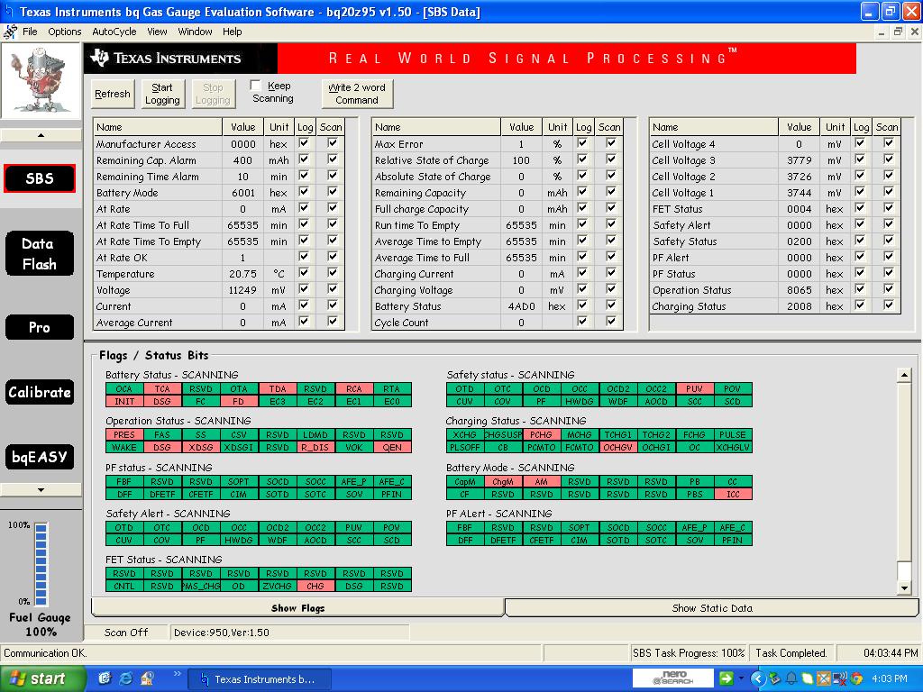
 Cell voltage 4 is showing 0 but at the pcm pad, voltage is available.

 am trying to make a pack of 4 cells in series(LFP 50ah each).I have assured it that i have connected each cells firmly. i have tried to calibrate voltage from calibration screen, but it keeps on showing 10.1V instead of pack voltage which shoyld be idelly 3.7*4= 14.8. i have tried Sbs command 004 also,but after that i am not able to connect the device with bqevsw.

i have come up with another issue immeditely before this,when GUI was recognising only 3cells. 

Please look over the issue.thanks

Kindly revert ASAP.

  • am trying to make a pack of 4 cells in series(LFP 50ah each).I have assured it that i have connected each cells firmly. i have tried to calibrate voltage from calibration screen, but it keeps on showing 10.1V instead of pack voltage which shoyld be idelly 3.7*4= 14.8. i have tried Sbs command 0040 also,but after that i am not able to connect the device with bqevsw.

    i have come up with another issue immeditely before this,when GUI was recognising only 3cells.

    Please look over the issue.thanks

  • did you program the operation cfg A register CC0 and CC1 bits correctly for 4 cells. Can you carefully measure and check the voltages on the VC1 input pins of the gauge to make sure it sees the voltage at top of highest cell and there is not a broken connection somewhere.


    If you have intermittent bad connection on top cell that would explain your earlier problem with charging or discharging.

    Did you already do a learning cycle and manually edit cycle count to 0 as i still want to understand how it seemed you sudenly  got MAX error =1% while cycle count is 0. Is this an old gauge IC  previously used on a different pack?  As I asked in other post please give me more back ground info.


  • Mike,i havent programmed any Config A or B as i have no idea that whtat should be done with them. please recommend as such document for this 4s configuration.one more thing short circuit protection isnt working on this module,when we tried to do so,the sense resistor burns out.
    thanks
  • Deepak,

    the technical reference manual for this part is http://www.ti.com/lit/er/sluu264a/sluu264a.pdf ,  see page 155 fig c6 to find the CC0 and CC1 bits.

    I am a bit concerned that it appears you have not configured any of the settings before connecting to cells and are damaging your sense resistor. The gauge can be used with 2,3 or 4 cells depending how you configure it, so it has to be prop[erly configured first before use . This includes all the thresholds like under , over voltage , plus many other settings that control charging , discharging , cell type etc etc.. In addition to above document you should check our bqEasy  guide http://www.ti.com/lit/ug/sluu278/sluu278.pdf?keyMatch=sluu278&tisearch=Search-EN.   bqEasy is the configuration tool in EVSW which should helps you set up number of cells and  other setting just y working through the screns it shows and answering questions about your application.

    Also http://www.ti.com/lit/an/slua334b/slua334b.pdf?keyMatch=slua334b.pdf&tisearch=Search-EN  is a good guide to doing learning cycle.

    Mike