This thread has been locked.

If you have a related question, please click the "Ask a related question" button in the top right corner. The newly created question will be automatically linked to this question.

Read and write from SD card in F28063

Other Parts Discussed in Thread: TMS320F28063, CONTROLSUITE, CSD

I'm referring the SD card interfacing document by Pradeep and Tim from TI at:

http://www.ti.com/mcu/docs/litabsmultiplefilelist.tsp?sectionId=96&tabId=1502&literatureNumber=spraao7&docCategoryId=1&familyId=919

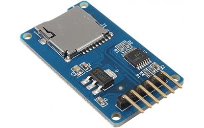
In the sample program, I have changed the device and example header file. I'm using clock of 80 MHz , 8 GB SDHC card and catalex card adapter.

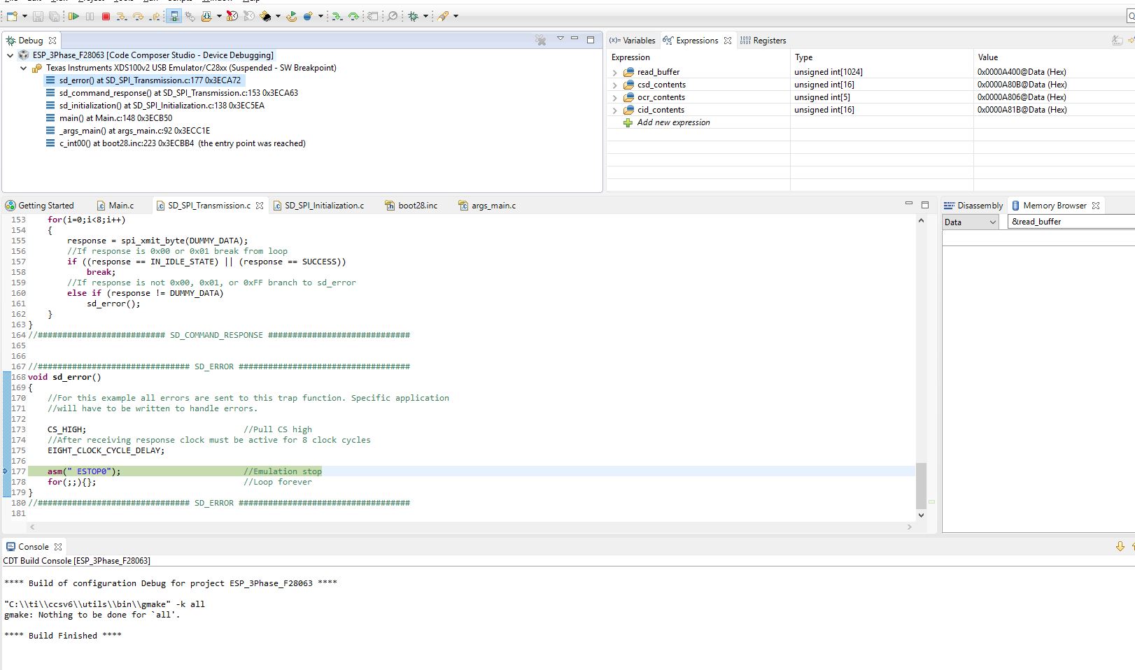
When I run the example program given by TI, I get error and program stops at asm(" ESTOP0");, 8 clock pulses were obtained :

//############################### SD_ERROR ###################################
void sd_error()
{    
    //For this example all errors are sent to this trap function. Specific application
    //will have to be written to handle errors.
    
    CS_HIGH;                                // Pull CS high
       //After receiving response clock must be active for 8 clock cycles
    EIGHT_CLOCK_CYCLE_DELAY;

   asm(" ESTOP0");                            // Emulation stop
       for(;;){};                                //Loop forever
}
//############################### SD_ERROR ###################################

If I comment the error lines:
   // asm(" ESTOP0");                            // Emulation stop
   // for(;;){};                                             //Loop forever

clock pulses are obtained but the select doesn't go low.

Please help on understanding SD card read and write from F28063 and suggest changes in program and hardware.

Hoping for a reply.

  • When does this sd_error() function get called? If you look at the call stack in the CCS Debug window, can you see what function called sd_error()?

    Thanks,
    Whitney
  • Sir,

    I have attached the image of debug window. I have commented the "sd_card_insertion();            //Check for card insertion" function. This error comes at least once in two attempts of debugging the code. I'm reading the data in "read_buffer". I want to know I'm I reading the data correctly? and which sectors of SD card can be used to write? as the write has been started from 0x0000 sector location.

    Please help.

  • Are you saying you removed the call to sd_card_insertion()? Why? Isn't that needed to provide the 74 cycle power up initialization?

    As you can see from the call stack, the error you're getting is coming from sd_command_response() which is waiting for the card to respond, saying its in the idle state. Can you put a break point in that function and see what the response value is that's making it jump to sd_error()?

    Whitney
  • Sir,

    I'm having 6 pins on my SD card adapter (clock, MISO, MOSI, Data, VCC and Ground), I'm not having the 7th pin for detection (as I'm having a micro SD card). That's why I commented the SD card detection pin at GPIO 34 in the function "sd_card_insertion".

    void sd_card_insertion()
    {
    Uint16 i;

    // while(GpioDataRegs.GPBDAT.bit.GPIO34 != 0){}; //Wait for Card A Insertion
    //After Card Detection, SD protocol states that card needs 74 clock 

    //cycles with the DATA IN line high for chip to stabilize. CS does not
    //need to be active for this action.

    CS_HIGH; //Pull CS high
    for(i=0;i<10;i++) //Transmit 0xFF for 80 clock cycles
    spi_xmit_byte(DUMMY_DATA);
    }

    When error is not there the response is "0xFF00" and When I get the error, response is "0x7F00" and "0xCA00" in the "sd_initialization" function at "sd_command_response" function where the response is checked at "else if (response != DUMMY_DATA)"

    void sd_command_response()
    {
    Uint16 i;

    RESET_RESPONSE; //Reset Response

    //This loop continously transmits 0xFF in order to receive response from card.
    //The card is expected to return 00 or 01 stating that it is in idle state or
    //it has finished it's initialization(SUCCESS). If anything is received besides
    //0x00, 0x01, or 0xFF then an error has occured.
    for(i=0;i<8;i++)
    {
    response = spi_xmit_byte(DUMMY_DATA);
    //If response is 0x00 or 0x01 break from loop
    if ((response == IN_IDLE_STATE) || (response == SUCCESS))
    {
    break;
    }
    //If response is not 0x00, 0x01, or 0xFF branch to sd_error
    else if (response != DUMMY_DATA)
    {
    sd_error();
    }
    }
    }

    Please can you tell me how is this error occurring (as it doesn't occur always) and what can I do to avoid it.

    Is the detection of SD card required. As I'm not having the 7th pin in the SD card adapter. Is it resulting in error.

    I'm using 8 GB micro SD card. I have read in the SD card interfacing document that parallel protocol is used for SD card > 2 GB capacity (I'm using SPI now). Here I have seen the "sd_version2_initialization" is been called as I'm using SDHC card.  I'm using low speed clock (LOSPCP) of 20 MHz and the value of register "SPIBRR =0x0063".

  • Hello,

    Okay, I understand the change you made to sd_card_insertion(). You're right--you don't need the detection pin. I was able to comment it out in the code and it still works fine for me. I am also using a microSD card with a capacity >2GB. I have not been able to reproduce the issue you're having though.

    Do you have the ability to use a logic analyzer or some other tool to make sure what is being read from the SPI registers is indeed what is being sent?

    Thanks,
    Whitney

  • Sir,

    I have attached the source code file. Please if you can it will be a great help for me to solve this problem. I'm not having a logic analyzer, but I'm having an oscilloscope.

    The waveforms observed of MOSI line doesn't take the form of the data which it sends and only remains high for the eight clock pulses. The received data (MISO) in the waveform is also not according to the clock pulses. I'm unable to understand this.

    I have tried to erase then write to SD card (in between the error occurs) and then tried to only read the data from SD card by removing the write and erase function in the for(;;) loop of main(), there the data which I was writing I was able to read the same data.  

    I'm reading the data in the read_buffer [] array. Is it correct way of reading the data from SD card?

    I have attached the images of scope.

    The code is in Source file folder, inside that main.c is the main source code and SD card files are in the src folder.  The scope images are attached below:

    Images from scope.rar

    Is it required to put external pull registers to MISO pin or any other pin ? The program files are attached below:

    SD card with F28063.rar

    Please suggest changes.

  • Hello,

    It's a little difficult for me to get much information from those oscilloscope captures without knowing the context of what the data is supposed to look like. For example, the one that shows MOSI staying high would be correct if it was supposed to be sending 0xFF (as it does when it's sending DUMMY_DATA while waiting for a response to be received).

    It's still not clear to me when the error is occurring. Are you no longer getting the error in sd_initialization()? Or is it inconsistent? Is it always in sd_command_response() or does it happen in different functions too?

    Yes, looking at read_buffer[] seems to be the correct way to see the data that has been read from the SD card. You should be able to change values in write_buffer[] in the expressions window, write it to the SD card, read the data back, and see it show up in read_buffer[] in the expressions window.

    The board I'm using doesn't seem to have any external pull-ups on MISO or MOSI although I do have the internal ones enabled (as do you in your code). It's possible that they aren't the right strength, so you could try disabling them and adding something externally.

    I've looked at your code and I don't see anything that is incorrect. You didn't make many modifications to the original app note code.

    Whitney
  • Sir,

    Thanks for your kind response and looking into my problems.

    Yes the error does occur in sd_command_response() as the response doesn't match IN_IDLE_STATE, SUCCESS or DUMMY_DATA values. Mostly the responses when error occured were "0x7F00" and "0xCA00".

    When I'm in debug mode, I changed the data of write_buffer[] and observed the changes in the read_buffer[] and the same data was seen. So when the code runs without errors, as I understand the data is being written and read correctly.

    If I can get through this error then I wanted to understand SD card sectors, so that I can write different data to different sectors or locations.
    e.g. sd_write_block(0x0000, write_buffer); //Write to sector zero
    sd_read_block(0x0000, read_buffer);

    //then
    sd_write_block(0x0010, write_buffer); //Write to sector ten
    sd_read_block(0x0010, read_buffer);

    But this results in change of data when written to different sectors (incorrect data is being read). But if I use single write command and that to different locations then I'm able to read the data correctly.
  • Hello,

    What kind of SD card are you using? Do you have another SD card you can try and see if the behavior changes at all?

    If the data seems to be correct on the oscilloscope but wrong when the device reads it, maybe adjusting the the clock phase and polarity would help. For example, you could try changing SPICCR from 0x0007 to 0x0047 in spi_initialization() and see if that makes any difference.

    I do have a concern about the code you sent me.  You had changed the buffer sizes to 100, but the reads and writes always seem to send 512 bytes at a time, so your reads are going to end up writing beyond the end of the read buffer and possibly corrupting some other data.

    Thank you for your patience.

    Whitney

  • Sir,

    I'm using SanDisk micro SDHC card of 8 GB.

    I tried by using a different SanDisk (8 GB, micro SDHC) card, but the error does come in at least two attempts of debugging the program.

    The data of MOSI and MISO lines I have checked on the scope and the data which I'm writing and reading is seen according to the clock pulses, when the program runs without error.

    I tried by changing the clock polarity in SPI settings to data out on falling edge, but read and write didn't happen.

    For reading 512 bytes as 1 sector are used. I tried to read and write 1024 values by using multiple block functions.

    I'm unable to get how the response in sd_command_response() is not proper and how to avoid it.

    Is the issue related to code ?
  • Sir,

    Is there anything else according to you which may be causing the improper response ?

    Hoping for a reply.
  • Hello,

    I apologize for the delayed response. It is difficult for me to debug since I am unable to reproduce the issue on my own board. I have done some web searches on the subject of failing initialization sequences and have an idea.

    I've read some descriptions of the GO_IDLE_STATE sequence and seen some example code that seem to suggest that receiving some garbage data in response before you get the IN_IDLE_STATE response is okay as long as you ultimately get the IN_IDLE_STATE response. Might be worth a try. I'm suggesting the following change to sd_initialization():

    Comment out:

        // while(response != IN_IDLE_STATE)        //Wait until card responds with IDLE response
        //     sd_command_response();

    In its place add:

        Uint16 i;

        for(i=0;i<8;i++)
        {
            response = spi_xmit_byte(DUMMY_DATA);
            //If response is 0x01 break from loop
            if (response == IN_IDLE_STATE)
            {
                break;
            }
        }

        //If response is not 0x01 branch to sd_error
        if (response != IN_IDLE_STATE)
        {
            sd_error();
        }

    I left the call to sd_error() for the sake of what would happen if it timed out of the for-loop without ever getting IN_IDLE_STATE. Let me know how that goes.

    Thanks,
    Whitney

  • Sir,

    I really appreciate your responses and taking your time for my problems.

    I made the changes as suggested, and the frequency of error reduced, at times I was receiving "0xFF00" response which resulted in error.

    I'm having a custom board made from TMS320F28063 IC, for debugging we are using JTAG (I have attached the image of JTAG). When I'm giving the 3.3 (V) required for the micro SDHC card from the JTAG, then I'm able read and write from SD card (with errors in response at times).

    When I use a power supply to generate 3.3 (V), then I'm unable to read and write from SD card. The response remains "0xFF00" and doesn't change to "0x0000" and "0xFE00". I have made the ground common.

    I'm also seeing now error occurring at sd_command_response() and if((send_if_cond_response[2] != SUPPLY_VOLTAGE) || (send_if_cond_response[3] != CHECK_PATTERN)) from sd_version2_initialization().

    Please suggest changes if I made any mistakes.

  • Hello,

    Have you tried slowing down the baud rate a bit and seeing if things improve?

    Have you studied the specs for the particular SD cards you're using to make sure the timing and clocking other properties are meeting the requirements? Have you experimented with different pull-ups?

    Whitney
  • Sir,

    I have tried by changing the baud rate and external pull ups, though the error does come at times.

    I will read documents related to SD card and see if I'm missing out on anything.
  • Sir,

    Thanks for your replies to my every queries.

    I haven't solved the problem of incorrect response from microSD card. I'm now working on that for more time.

    If I have a value written in one of the sectors of microSD, then how should the value be stored it a text or excel format? Is there any support for such implementation?

    Is FAT32 required for this?

    As you had suggested to look for "controlSUITE\device_support\F2837xD\v200\F2837xD_examples_Cpu1\sd_card" example. This example seems to read files from microSD.

    One problem I had faced was: when the data was written in microSD using "http://www.ti.com/apps/docs/litabsmultiplefilelist.tsp?literatureNumber=spraao7&docCategoryId=1&appId=270" example, Windows was unable to read the data in the card and was asking to format the card due to unsupported content. 

    I have to write data in a format which should be supported by Windows.

    Please provide the necessary guidance.

  • That controlSUITE example that you referred to shows the use of the FatFs. I recommending looking into that.

    elm-chan.org/.../00index_e.html

    Whitney
  • Sir,

    I'm able to create a .txt and .csv file in the microSD, but I'm unable to write into the file which is created. The file size is 0 B, so no data is being written in the file.

    There are many functions within f_write() which are linked with "mmc-F2837x.c" file. 

    WORD  bw;

     f_write(&g_sFileObject, "It works!\r\n", 11, &bw);

    Trying to debug through this problem. 

  • With what flags are you calling f_open? If you step through f_write, can you determine when exactly the error is received?

    Thanks,
    Whitney
  • Sir,

    Thank you for your reply.

    By debuging I'm reaching:


    if (count == 1) /* Single block write */
    {
    if ((send_cmd(CMD24, sector) == 0) /* WRITE_BLOCK */
    && xmit_datablock(buff, 0xFE))
    count = 0;
    }

    in 

    /*-----------------------------------------------------------------------*/
    /* Write Sector(s) */
    /*-----------------------------------------------------------------------*/

    #if _READONLY == 0
    DRESULT disk_write (
    BYTE drv, /* Physical drive nmuber (0) */
    const BYTE *buff, /* Pointer to the data to be written */
    DWORD sector, /* Start sector number (LBA) */
    BYTE count /* Sector count (1..255) */
    )
    {
    if (drv || !count) return RES_PARERR;
    if (Stat & STA_NOINIT) return RES_NOTRDY;
    if (Stat & STA_PROTECT) return RES_WRPRT;

    if (!(CardType & 4)) sector *= 512; /* Convert to byte address if needed */

    SELECT(); /* CS = L */

    if (count == 1) /* Single block write */
    {
    if ((send_cmd(CMD24, sector) == 0) /* WRITE_BLOCK */
    && xmit_datablock(buff, 0xFE))
    count = 0;
    }
    else /* Multiple block write */
    {
    if (CardType & 2)
    {
    send_cmd(CMD55, 0);
    send_cmd(CMD23, count); /* ACMD23 */
    }
    if (send_cmd(CMD25, sector) == 0) /* WRITE_MULTIPLE_BLOCK */
    {
    do
    {
    if (!xmit_datablock(buff, 0xFC)) break;
    buff += 512;
    }
    while (--count);
    if (!xmit_datablock(0, 0xFD)) /* STOP_TRAN token */
    count = 1;
    }
    }

    DESELECT(); /* CS = H */
    rcvr_spi(); /* Idle (Release DO) */

    return count ? RES_ERROR : RES_OK;
    }
    #endif /* _READONLY */

    ////////////////////////////////////////////////////////////////////////////////////////////////////////////////////////////////////////////////////

    and
    if ((send_cmd(CMD24, sector) == 0) /* WRITE_BLOCK */
    && xmit_datablock(buff, 0xFE))
    the above condition fails. send_cmd() returns res= 0. xmit_datablock() returns FALSE.

    This results in:

    if (clust == 1 || clust >= fs->max_clust)
    goto fw_error;

    as clust is 1 in f_write()

    /////////////////////////////////////////////////////////////////////////////////////////////////////////////////////////////////////////////////////

    I didn't get wait_ready() in mmc-F2837x.c.

    /*-----------------------------------------------------------------------*/
    /* Wait for card ready */
    /*-----------------------------------------------------------------------*/

    static
    BYTE wait_ready (void)
    {
    BYTE res;


    // Timer2 = 50; /* Wait for ready in timeout of 500ms */  // I have removed this and used

    t_1ms = 0;
    rcvr_spi();
    do{
    res = rcvr_spi();
    DELAY_US(175);
    } while ((res != 0xFF) && t_1ms <499);

    return res;
    }

    %%%%

    Uint16 t_1ms; is incremented by 1 in timer ISR in 1msecs. 

    /////////////////////////////////////////////////////////////////////////////////////////////////////////////////////////////////////////////////////

    Whitney Dewey said:
    With what flags are you calling f_open? 

    I'm using:

    if (f_open(&g_sFileObject, "filename.txt", FA_WRITE | FA_CREATE_ALWAYS) == FR_OK)

    before using f_open(), I have used function from example

    InitSpiaGpio();

    spi_initialization();

    sd_card_insertion(); //Check for card insertion
    sd_initialization(); //Initialize card

    sd_read_register(SEND_CSD); //Read CSD register
    sd_read_register(READ_OCR); //Read OCR register
    sd_read_register(SEND_CID); //Read CID register

    I'm not using the console made using UART.

    /////////////////////////////////////////////////////////////////////////////////////////////////////////

    I have attached the image of debug window. Please suggest if I'm doing wrong.  

  • Okay, I'm seeing a similar issue. For me, xmit_datablock() is returning false because the condition ((resp & 0x1F) != 0x05) is true (I think resp is 0xFF). Is that what you're seeing?

    Haven't had a chance to debug any further than that yet.

    Whitney
  • Sir,

    Sorry for the late reply. Yes as you have said

    Whitney Dewey said:
    xmit_datablock() is returning false because the condition ((resp & 0x1F) != 0x05) is true (I think resp is 0xFF).

    I can also get the same response. I have attached image of debug window of the same issue.     

    I have not used wait_ready(). Is the delay required?

  • Take a look at:
    e2e.ti.com/.../489133
    e2e.ti.com/.../1484512

    Worked for me like a charm
  • I made the change suggested above (change wc = 0 to wc = 256) and it solved my problem.

    Whitney
  • Sir,

    Thanks for the valuable information.

  • Sir,

    Thanks for looking into my problems.


    I have changed wc = 0 to wc = 256, but I'm getting cstat =1 in
    cstat = get_cluster(fs, ncl); /* Get the cluster status */
    if (cstat == 1) return 1; /* Any error occured */

    as move_window() within get_cluster() returns false 

    if (sector) {
    if (disk_read(fs->drive, fs->win, sector, 1) != RES_OK)
    return FALSE;

  • Whitney Dewey said:
    I made the change suggested above (change wc = 0 to wc = 256) and it solved my problem.

    Sir,

    Which device are you using? I'm trying on F28069.

  • I've been doing my testing with an F2837xD controlCARD because it has a microSD card slot on it. I don't currently have an SD card breakout board so I haven't been able to test with the F28069. However, there are only minor differences between their SPI modules, none of which seem to be things that would effect the FatFS port.

    Whitney
  • Sir,

    I'm able to write to .txt and .csv created file (using , (commas) for changing columns and \n for new row) on the F28069 device.

    I wanted to know, how to read the amount of free memory space so that data can be written until space is available ?

    what would be the timing required to write to microSD card, so that write operation of logging data should not affect the main operation of the DSP?
  • In .csv file, if 5 rows have been written, then how to write data from 6th row on a specific condition. I have tried by using f_sync(). I wanted to know whether is this the way how it's done?

    Please someone guide me.

  • Please can you tell me whether pull-ups resistor are required at MISO and CS?

    I have connected pins directly to the microSD card adapted from F28069 device, And at times the program does stuck at 

    if (f_open(&g_sFileObject, "file.txt", FA_WRITE | FA_CREATE_ALWAYS) == FR_OK) { /* Create a file */

  • I don't know about CS, but everything I've read says you'll need one on MISO to avoid failures in the initialization process.

    Whitney

  • Sir,

    The Catalex microSD card adapter seems to be getting damaged when I'm using pull-up on MISO, and returns card not ready error and fails the file creation on the card f_open().

    As I said the program at times gets stuck at

    if (f_open(&g_sFileObject, "file.txt", FA_WRITE | FA_CREATE_ALWAYS) == FR_OK) { /* Create a file */

    }

    If I press the pins on the adapter then the above condition becomes true. I have attached the image of the adapter. I'm looking into it, please if you can suggest something, than it can be helpful.

  • Ravi,

    Were you able to resolve the issue? It sounds like there may be a hardware problem, as physically pressing on the pins seems to affect the performance. If you have a magnifying glass or microscope and soldering iron available, investigate the SD Card board for poor solder connections.

    If you are still experiencing an issue, please let us know.
  • Sir,

    I made a PCB for the card adapter and driver and the data write is running smoothly for now.
    Currently I'm facing issues with the implementation of data log, maybe experts can help me on this.

    I wanted to write headers in the first row which will be followed by data. The headers will only be printed once and the data will be written thereafter. So I was trying to write the header once and was trying to save the file size "g_sFileObject.fsize" in an EEPROM. After that I remove the writing of headers from the code and then use
    f_lseek(&g_sFileObject, append); // append is the stored g_sFileObject.fsize
    thereafter.
    By doing so I'm able to write the data after headers, but a line of garbage appears in the .csv file:
    -----------------------------------------------------------------------------------------------------------------------------------------------------------------
    *Saved from Unit #: 23-2-17/1Time:

    On Date: 24/02/2017/ Time: 19:45:15 Write succesful
    On Date: 24/02/2017/ Time: 19:48:52 Write succesful
    On Date: 24/02/2017/ Time: 19:49:52 Write succesful
    On Date: 24/02/2017/ Time: 19:49:52 Write succesful
    On Date: 24/02/2017/ Time: 19:50:51 Write succesful ¦¹ ç^^ý‹³V³…ÕÿíyuÍù‰55ÑÉ»ÞowÑÝ/êÀ$feà@6–#\¸1çv€ÜnZf»Æ›hkx(¿`rÇÐ{0ao
    On Date: 25/02/2017/ Time: 09:17:35 Write succesful
    On Date: 25/02/2017/ Time: 09:18:35 Write succesful
    On Date: 25/02/2017/ Time: 09:19:34 Write succesful
    On Date: 25/02/2017/ Time: 09:21:46 Write succesful
    On Date: 25/02/2017/ Time: 09:22:45 Write succesful
    On Date: 06/03/2017/ Time: 14:19:33 Write succesful
    On Date: 06/03/2017/ Time: 17:03:20 Write succesful
    On Date: 06/03/2017/ Time: 17:04:20 Write succesful
    On Date: 06/03/2017/ Time: 17:05:19 Write succesful
    ----------------------------------------------------------------------------------------------------------------------------------------------------------------
    It would be helpful if anyone can suggest me on how this can be implemented.