This thread has been locked.

If you have a related question, please click the "Ask a related question" button in the top right corner. The newly created question will be automatically linked to this question.

OPA1692: About the behavior when the output is saturated

Part Number: OPA1692
Other Parts Discussed in Thread: OPA2134, OPA2197, OPA1642

I use OPA1692 to connect multiple audio amplifier circuits with different gains in parallel. That is to accommodate all input levels. The input sides of multiple amplifier circuits are connected to each other and are not switched by a switch. Therefore, all amplifier circuits operate at the same time for all inputs.

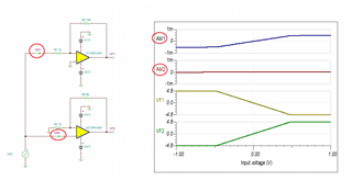
For example, I choose a small gain amplifier circuit output for large inputs. At that time, the output of the unselected amplifier circuit with a large gain is saturated.
I measured the audio distortion, but the amplifier circuit with saturated output exacerbates the distortion of the audio signal on the input side.

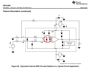
I tried the amplifier circuit configuration with inverting, non-inverting, instrumentation amplifiers, but the circuit configuration had no effect. I think that when the output is saturated, it has some effect on the input side. And that seems to happen when Opamp's architecture is Bipolar and not when it's FET.

If the output is saturated
1. What is the mechanism behind this problem within Opamp? The distortion degradation on the input side is not monotonous with respect to the input level.
2. What is the impact of Opamp's architecture?
3, I want to use the bipolar type because of noise. Is there a way to avoid distortion leakage to the input side? Due to CPU limitations, it is difficult to switch the amplifier circuit on the input side or switch the gain, so I would like to solve this problem with hardware alone, without using software.
The power supply is used at ± 5V.

Best Regards,
Yukio Oyama

  • The issue you face is most likely caused by turning on of the back-to-back input protection diodes present betweeen the OPA1692 input terminals - see below.

    As you slam the output against one of its rails, the op amp cannot maintain a virtual short between the input terminals and the voltage at the inverting input gets set by the ratio of gain resistors.  Since most bipolar op amps including OPA1692 require back-to-back protection diode, this condition causes a current flow through one of the input diodes resulting in the distortion in other op amps connected in parallel. 

    Instead please consider using JFET input op amps like OPA1642 and OPA2134, or CMOS like OPA2197.

  • Thanks for your answer.


    I realized that the input protection diodes are affecting this issue.
    Is the FET input Op amp not facing this issue because there is no input protection diode? I searched for a datasheet that is written the internal circuit of the FET input Op amp, but couldn't find it. Do you know the material?


    I still have the question that distortion leakage to the input is not monotonous with increasing input level. Is it because the output voltage clips to the power supply, so the inverting input voltage (which is set by the ratio of the gain resistance to the output voltage) does not exceed the input voltage for a longer period of time as the input increases?

  • Yes, most JFET input amplifiers, like OPA1642 and OPA2134, do NOT need back-to-back input protection diodes – they are self-protected.  However, most CMOS input amplifiers may need those diodes - exception is in the case of 'MUX friendly' op amps like OPA2197.

    In order to be fully immune to "distortion leakage" you must use a non-inverting circuit configuration.  Using inverting configuration is susceptible to output current loading variation being non-monotonous (see AM1), which will cause distortion in the case of multiple op amps being connected in parallel.  Using a non-inverting configuration for all practical purposes completely eliminates the input current variation (AM2) - see below.


    Yukio OPA1642.TSC

  • I could not completely prevent distortion leakage even with a non-inverting circuit configuration. Is it correct to conclude that the presence of back-to-back input protection diodes cannot completely prevent distortion leakage?
    I thought it would be necessary to use an op amp without an input protection diode or buffer the input to isolate it in parallel from the op amp to prevent this problem.
    Do you have any other solution?

  • I'm sorry, I made a mistake. Correctly,
    "Is it correct to conclude that distortion leakage cannot be completely prevented as long as back-to-back input protection diodes are present?"

  • That is correct. With back-to-back (b2b) input protection diodes, regardless of the configuration used, there is always a current path from the input terminal to the output causing distortion.  Thus, in order to eliminate the issue you must use an op amp without b2b diode and only in a non-inverting configuration.

  • Thank you for your answer.
    I've got some useful information and I'll use it to come up with a solution.
    I close this case.
    Thank you very much