This thread has been locked.

If you have a related question, please click the "Ask a related question" button in the top right corner. The newly created question will be automatically linked to this question.

TLV320AIC3268: Coefficient Loading, Part 2

Part Number: TLV320AIC3268

Dear TI Professional,

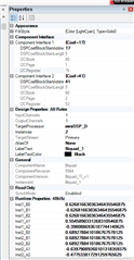
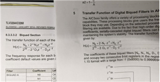
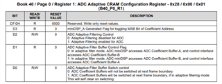
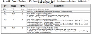
Okay. I now have my coefficients and they are looking pretty good. Now, it is time to do the upload. I have been reading the document, SLAA447, and this has been very helpful.  When using PPS, it tells me my first BiQuad instance coefficients are loaded at location Book 80 (0x50), Page 1 (0x01, and beginning Register 76 (0x4C).  First of all, looking at PPS (see image below), the digits appear to be in 3.23 format. SLAA447 says it should be a 1.15 data format. Secondly, the data in the register settings does not appear to match the Inst1_B0..Inst1A2 values as shown in PPS. Is this because the data we are setting are N0, N1, N2, D1, and D2 instead?

One more question. Is this the basic sequence necessary to read these values:
  w 30 00 00
  w 30 7F 50
  w 30 00 01
   r 30 4C          (returns the value of N0, MSB)
   r 30 4D          (returns the value of N0, LSB)
   ...

Thank you for your assistance.

Phil

  • Here is my code so far:

    void SetLowPass(unsigned int freq)
    {
    	double Fs = 48000;					// Sample Frequency
    	double f0 = freq;					// Corner frequency (provided input)
    	double dBGain = 0;					// Gain applied to frequencies within range
    	double Q = 0.707;					// Quality constant. 0.707
    	double w0, alpha, sinW, cosW;		// Intermediate calculated parameters
    	double b0, b1, b2, a0, a1, a2;		// Calculated BiQuad Coefficients
    	double B0, B1, B2, A1, A2;			// Normalized BiQuad Coefficients
    	double B0new, B1new, B2new;			// Scaled Coefficients so N0, N1, and N2 are less than 1
    	double N0, N1, N2, D1, D2;			// Calculated Continuous Coefficients
    	double Mx;							// Absolute Maximum Value of 3 Coefficients
    	unsigned char NB = 16;				// Number of Databits of Coefficients
    	unsigned char Range;
    	short N0_1Dot15, N1_1Dot15, N2_1Dot15;	// N0..N2 Conversion to 1.15 Format
    	short D1_1Dot15, D2_1Dot15;				// D1 and D2 Conversion to 1.15 Format
    
    	// Calculate intermediate Parameters
    	w0 = 2*PI*f0/Fs;
    	cosW = cos(w0);
    	sinW = sin(w0);
    	alpha = sinW/(2*Q);
    
    	// Calculate Low Pass Filter Coefficients
    	b0 = pow(10,(dBGain/20))*((1 - cosW)/2);
    	b1 = pow(10,(dBGain/20))*(1 - cosW);
    	b2 = pow(10,(dBGain/20))*((1 - cosW)/2);
    	a0 = 1 + alpha;
    	a1 = -2*cosW;
    	a2 = (1-alpha);
    
    	// Normalize so that A0 = 1
    	B0 = b0/a0;
    	B1 = b1/(2*a0);
    	B2 = b2/a0;
    	A1 = a1/(-2*a0);
    	A2 = a2/(-a0);
    
    	// Scale Coefficients for Normalized largest of values is less than 1
    	Mx = Maxf(B0, B1, B2);
    	if (Mx > 1.0)
    	{
    		B0new = B0/Mx;
    		B1new = B1/Mx;
    		B2new = B2/Mx;
    	} else
    	{
    		B0new = B0;
    		B1new = B1;
    		B2new = B2;
    	}
    
    	// Convert Scaled Continuous Coefficients to Quantized Coefficients
    	Range = 2^(NB-1)-1;
    
    	N0 = floor(B0new*Range);
    	N1 = floor(B1new*Range);
    	N2 = floor(B2new*Range);
    	D1 = floor(A1*Range);
    	D2 = floor(A2*Range);
    
    	// Convert N0-D2 into 1.15 Format Integers (required data format TLV320AIC3268 DSP coefficients
    	N0_1Dot15 = Floatto115(N0);
    	N1_1Dot15 = Floatto115(N1);
    	N2_1Dot15 = Floatto115(N2);
    	D1_1Dot15 = Floatto115(D1);
    	D2_1Dot15 = Floatto115(D2);
    
        // Now, upload these new coefficients into the DSP at the location of the Low Bandpass BiQuad Instance.
    
    	// Begin by setting DSP into Adaptive Filtering for DAC (DAC won't accept the new changes otherwise)
    
    
    }

  • Correction.

    Line 54:  Range = pow(2, (NB-1)) - 1;

    In MATLAB the ^ symbol raising x to the y power (exponentiation). In C, this is a logical bitwise XOR. Quite different. One must use the pow() function.

  • Incidentally, I get the proper low band filter coefficients when compared to the sample in SLAA447. My only question is how to know the register locations.  Since I used PPS to configure the BiQuad, I suspect I need to pay attention to where PPS says we should set the parameters. SLAA447 says these coefficients should be in 1.15 format. It looks from the PPS screenshot above that the coefficients are in 3.23 format. Is PPS back calculating the b0, b1, b2, a1, a2 values from the N0, N1, N2, D1, and D2 values uploaded?  Is this what I am seeing?

  • Isn't adaptive filtering already enabled in the TLV320AIC3268 since I am using the DAC?  Do I need to still set the adaptive filtering mode on Page 8?

  • If we are using Adaptive Filtering, shouldn't there be two sets of buffers?  What is the address of the second butter?

  • Just noticed this discrepancy.  See image below. One is document SLAA447 and the other is SLAS953A (TLV320AIC3268 datasheet. The transfer function in the datasheet is using a 24-bit, 3-Byte data word; more like a 1.23 data format.

  • Hey Phil,

    I think the app note you are referencing is still useful, but it was not written explicitly for the AIC3268. Some miniDSP devices have a 16-bit DSP while AIC3268 has a 24-bit DSP. It sounds like you have figured that out already but sorry for the confusion. I believe your register read sequence is okay.

    The adaptive filtering mode can be independently enabled/disabled for the ADC and DAC sections depending on where the filter you are programming resides. Adaptive filtering is enabled in book 40 page 0 register 1 for the ADC and book 80 page 0 register 1 for the DAC

    You should be able to write the biquad coefficients directly, just keep in mind that B1 and A1 need to be half of the intended value since they are multiplied by 2 in the transfer function.

    Best,

    Zak