This thread has been locked.

If you have a related question, please click the "Ask a related question" button in the top right corner. The newly created question will be automatically linked to this question.

TLV320ADC3140: [TLV320ADC3140] TDM mode can't record by dmic

Part Number: TLV320ADC3140

Hi,team

We use your EVM board which can work well in slave or master TDM.

But now factory has produced formal boards.

There is hardware difference:

1)EVM some power is use 3.3v like AVDD,but our board all power use 1.8v

2)EVM use analog MIC,and we use 8 DMIC.

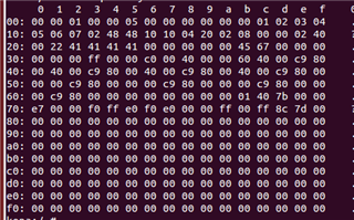
According to the document tlv320adc3140.pdf, i config following regs:

slave mode:

0x02 0x01      // power

0x3c 0x40       //mic setting
0x41 0x40
0x46 0x40
0x4b 0x40

0x22 0x41      //GPO   setting
0x23 0x41
0x24 0x41
0x25 0x41

0x41 0x48     // default 48K 12.288M

0x2b 0x45     //GPi   setting
0x2c 0x67
0x73 0xff
0x74 0xff
0x75 0x60

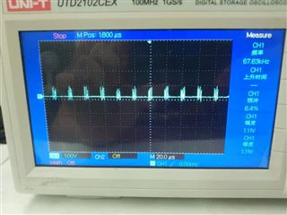
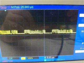
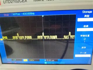
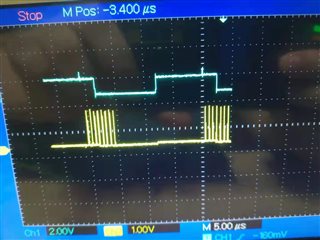
Now the DMIC can get 3M CLK and output data.

But record data is NULL,i think ADC output data have problem.

ADC maybe output null data.

Please help check it.

thanks

  • Hi Zeng,

    I don't see any issues in the script you are using. Can you confirm that AREG and AVDD are shorted together on your board? If AREG is not sourced internally it needs to be connected to the same source as AVDD. I assume the DMICs are also using the same 1.8V supply?

    Best,

    Zak

  • Hi,Zak

    Yes,AREG is connect AVDD.

    There is the status:

    IOVDD  1.8V
    DREG  1.45V
    AVSS   GND
    VREF  1.75v
    AREG  1.75v
    AVDD  1.75v
    DMIC_ VDD 1.8V
    DMIC_ CLK 3.072M

    And i also Change J3 to 1.8v,the EVM can work well.

    I find a strange point.

    Our board ceiling voltage

    BCLK:0.9V

    DATA:0.9V

    EVM ceiling voltage

    BCLK:2.3V

    DATA:3.3V

    When i shorted board BCLK with board DATA,i can't record the data.

    But if i shorted EVM BCLK with board DATA,i can record the data.

    Even the data is noise.

    I think the problem is ADC output voltage is too low

    Do you have any suggestions about this phenomenon?

    thanks

  • Hi Zeng,

    You said you are testing your board in slave mode, correct? If you're applying BCLK and FSYNC and these are only signaling as 0.9V for a high level this is not going to be detected as a high by the device. I'm not sure why you would short BCLK to DATA, this is not a condition that should ever occur. 

    Can you confirm what you read back from the ASI_STS register 0x15? It would also be helpful to check register 0x76 and 0x77.

    Best,

    Zak 

  • Hi,Zak

    Yes,we are config slave mode now.

     I'm not sure why you would short BCLK to DATA, this is not a condition that should ever occur. 

    >>>

    This is a test.

    1)EVM BCLK is 2.3V which is connect data line can record noise.

    2)Our board BCLK is 0.9V which connect data line can't get sound.

    Our data also just have 0.9V,that means our board data voltage is too low.

    And I think this is why we can't record.

    There is regs map:

    From the 0x73 and 0x76.some channel can't enable.

    From hardware team info,our board have four ADC IC.

    Even now we just test one ADC,but maybe data driver power is low.

    Did we have register config for increase data driver voltage?

    thanks

  • Hi Zeng,

    DOUT and BCLK are both actively driven lines and unless there is sufficient resistance between the pins it is not advised to drive a signal into DOUT when it is not in a high impedance state. If the drive current is sufficient this could damage the output.

    If your board BCLK is 0.9V it sounds like you aren't using valid logic levels or your driver doesn't have the strength to drive the clock lines to the intended voltage. Our device has sufficient drive strength to support up to 64 devices on the same bus so I am confident DOUT drive strength is not the issue.

    Best,

    Zak

  • Hi,Zak

    After hardware team change the resistance,the problem is resolve.

    Now the slave(12.288M) and master(24.576M) can record sound.

    But the record data seem just get one DMIC data.

    0x73 and 0x76 both are 0xf0,Is that the reason?

    thanks

  • Hi Zeng,

    Is your master device running at a different rate than the slave device? I'm confused why you are giving 2 different clock frequencies. It looks like you have only enabled 4 channels of data, and each GPI pin carries 2 channels so only inputs 1 and 2 would be active. Also note that if you are using 8 channels of PDM mics you need to disable the biquads in the DSP_CFG1 register (0x6c), otherwise, channels 7 and 8 will show excessive delay. 

    Best,

    Zak

  • Hi,Zak

    I'm sorry I didn't describe it clearly.

    Now we config one ADC master mode(24.576M),and other two ADC is slave mode.

    We have two problem

    1)Our use 8 PDM,I have config reg 0x73 and 0x74 to 0xff.

    But from 0x73 and 0x76 status,we just use 4 PDM (4 channel)

    Please help check it.How can we enbale 8 channel.

    2)Actually, I'm not sure record files channel(slot) number.

    Becuase this data files is 48K 512bit which inculde 32 channel.

    We can't normal playback it.

    How can we confirm it?

    I noticed data line have four peak value,is that mean have 4 channel data?

    thanks

  • Hi Zeng,

    Have you verified the clocks from the master device are correct? Are you sure FSYNC is being configured for 48kHz operation? 0x73 is not a status register, it is the input channel enable register. If you are not setting 0x73 to 0xff then you will not see all 8 channels on the bus.

    Best,

    Zak

  • Hi,Zak

    Some audio alsa codes change the regs.

    After i change codes,the status is ok.

    Now we config one ADC as master mode.Tow ADC is slave mode.

    Change 0x0b ~ 0x12 for three ADC slot offset.

    ADC1  0 ~ 7  slot

    ADC2  8~15  slot

    ADC3  16~23 slot

    There is the data.SYNC is 48K,so 20us is a buffer.

    We can get 15us(24slot) data.

    But sometimes the data will overlap.Please check the protruding voltage

    I think it may be that the frequency is too high.

    Could you help doubile check the result?

    thanks 

  • Hi Zeng,

    I would make sure that you are programming each of the devices to set its DOUT line in HiZ when not actively driving data. Since you are not using all of the available clock cycles you might also consider adding a cycle or 2 of offset to each of the TDM outputs to help ensure there won't be any timing issues. 

    Best,

    Zak

  • Hi,zak

    Yes we have set data to HIZ by 0x07(set to 0x09 or 0x01)

    Now we have a problem about the timing

    If we just enable one ADC(master),we can get 8 normal channel

    But if we add other ADC(slave) ,all channel data is noise.

    Because ADC slot position si not  fixed.

    Even we set ADC to 0~7 slot(0x0b ~0x12),but the slot can be any other slot  position

    Please help check the problem.


    thanks

  • Hi Zeng,

    It sounds to me like you are not setting the slot offset for the other devices on the bus? Please refer to this app note for sharing the TDM bus: https://www.ti.com/lit/an/sbaa383b/sbaa383b.pdf

    You may also need to verify that all of the devices are set for the same 16-bit TDM format.

    Best,

    Zak

  • Hi,Zak

    We can record 24 channel data.

    The problem is cause by sync mode is not correct.

    We need set 0x07 to 0x09

    thanks

  • Hi Zeng,

    I am glad you were able to resolve the issue!

    Best,

    Zak