This thread has been locked.

If you have a related question, please click the "Ask a related question" button in the top right corner. The newly created question will be automatically linked to this question.

TAS2505-Q1: Circuit Design Inquiries (IOVDD, Internal LDO)

Part Number: TAS2505-Q1
Other Parts Discussed in Thread: TAS2505

Hi, TI Support Team

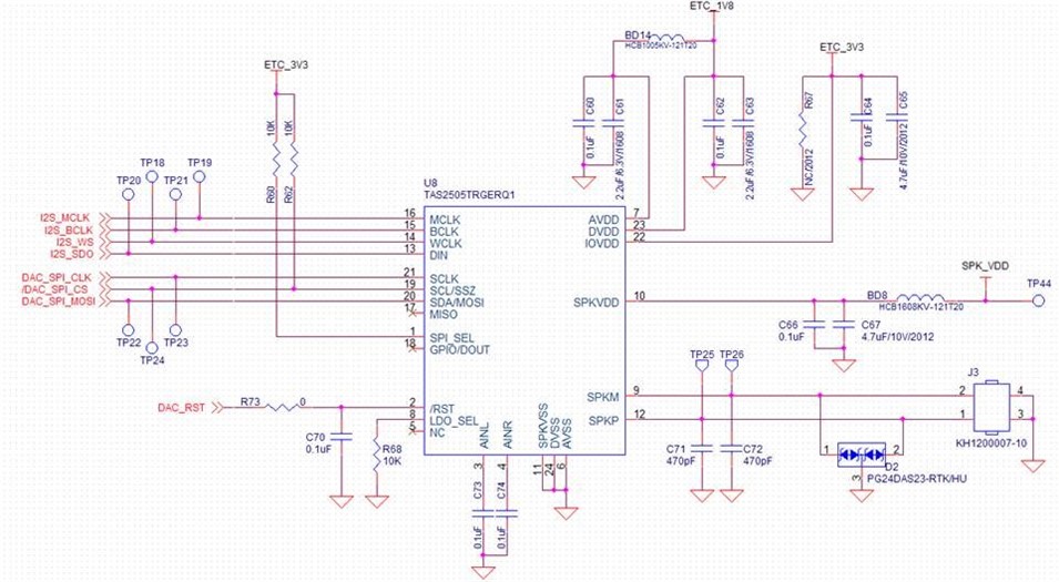
A customer is reviewing a design using the TAS2505TRGERQ1.

Please check the inquiries below.

1. Is it correct to connect the IOVDD (22th pin) pin to 3.3V to set the MCU and SPI interface to 3.3V?

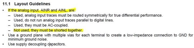
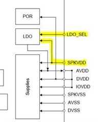
2. You want to use an internal LDO.

Connecting the LDO_SEL pin to SPKVDD is specified in the datasheet.


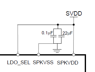
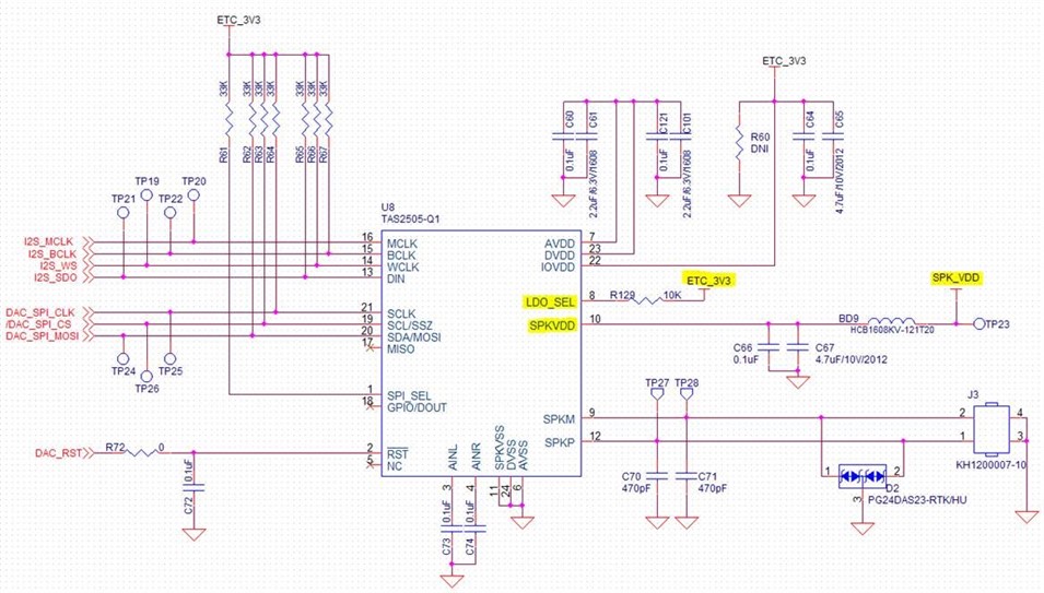
Is there any problem with the circuit configuration as shown below?

- I want to control ON/OFF of 5V supplied to SPKVDD using FET switch. (to remove speaker output noise)

- Because of the above configuration, when the LDO_SEL pin is connected to SPKVDD, 5V is not normally supplied, but only when the voice is output. (Refer to the circuit below)

- Is it okay to connect the LDO_SEL pin to an external 3.3V?


3. Looking at the datasheet block diagram, is LDO_SEL the ON/OFF signal and the POWER SOURCE of LDO is SPKVDD?

Please confirm the above inquiries.

Thanks.

Regards,

MJ

  • Hello MJ, 

    Yes, the IOVDD set to 3.3V will also set the SPI and other I/O signals to 3.3V logic. 

    As for the LDO, I would recommend using an external LDO for this application. We are in the process of releasing a datasheet update for the TAS2505 that changes the LDO recommendations for this part and it should be available online soon. 

    As for having SPKVDD switching, one concern with this is the additional time for powering on the device each time. The TAS2505 can power down the speaker driver based on an internal register, is powering down the output this way not enough for this application? If that is the case, keep in mind that each time the TAS2505 is powered on, the same power sequence and register configuration will need to be applied. Otherwise, I don't have any concerns with doing this. 

    You are correct that the LDO does take power from the SPKVDD and the LDO_SEL is just an ON/OFF enable pin. 

    Best Regards, 

    Justin Beigel

  • Hi, Justin

    Thank you for reply.

    Customers have additional inquiries.

    AVDD: 22uF

    DVDD: 10uF

    SPKVDD: 22uF

    IOVDD: 10uF

    I am trying to use a lower value than the CAP value shown in the application circuit diagram, but what is the minimum value?

    If you look at 8.4.8 5V LDO in the datasheet, it is mentioned that AVDD and DVDD use 1uF or more.

    If you look at the schematic, I used 2.2uF and 4.7uF, is that ok?

    Thnaks.

    Regards,

    MJ

  • Hi, Justin

    I have additional questions.

    A customer wants to use an internal LDO.

    What issues are you concerned about if you use an internal LDO?

    If parts are added, the unit price of the product will increase, so please inquire.

    If a serious problem occurs, we will review the use of an external LDO.

    please answer about my question.

    Thanks.

    Regards,

    MJ

  • Hi, Justin

    If an external LDO is used, what is the maximum Current Spec?

    Thanks.

    Regards,

    MJ

  • Hello MJ, 

    We recommend using the larger capacitor values but the ones you mentioned should be fine. One thing I will point out is we do recommend having capacitors that are rated for 5x the rail voltage for the power rails. 

    If you accept my friend request, I can send you a PPT with more information about the internal LDO. 

    As for external LDO current, you should not need more than 50mA for AVDD and DVDD. 

    Best Regards, 

    Justin Beigel

  • Hi, Justin

    There was a request for review of the revised schematic from the customer.

    The circuit diagram has been modified by applying 1.8V to the external LDO, and please check if there is any problem with the interface

    mentioned below.

    - 3.3V SPI interface with MCU

    - I2S 3.3V interface

    In addition, SPK_VDD will be decided after testing on how to control ON/OFF with an external switch (FET) and internal resistor.

    Thanks.

    Regards,

    MJ

  • Hello MJ, 

    I have a couple notes for the schematic:

    • As I previously mentioned, we recommend having capacitors rated for 5x the rail voltage. for a 5V rail, this would be a 25V rated capacitor. 
    • If you aren't using the AINL/R, you can just short them together rather than having the capacitors to GND. 
    • We normally see LC filters on the output for EMI concerns. If the customer decides to move from just capacitors to an LC filter, we have the LCFILTER-CALC-TOOL available to help with this. 

    Otherwise, the schematic looks good. 

    Best Regards, 

    Justin Beigel

  • Hi, Justin

    Thnak you for reply.

    I have additional questions.

    If AINR and AINL are not used, how should the pins be handled?

    The information in the datasheet below is shorted.

    Please confirm.

    Thanks.

    Regards,

    MJ

  • Hello MJ, 

    The datasheet is correct. You should short the two pins together if you are not using the analog input. 

    Best Regards, 

    Justin Beigel