This thread has been locked.

If you have a related question, please click the "Ask a related question" button in the top right corner. The newly created question will be automatically linked to this question.

TPA3255: IMD at TPA3255 inputs

Part Number: TPA3255

Hello,

I have TPA3255 circuit that is giving me pretty high IMD when I feed in 13kHz + 15kHz dual tone signal. 

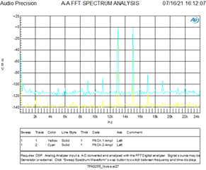
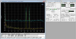
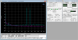
The strange thing is that when measured differentially across TPA_INPUT_A / TPA_INPUT_B, the spectrum looks pretty good:

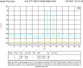
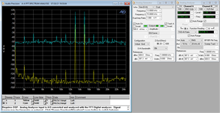
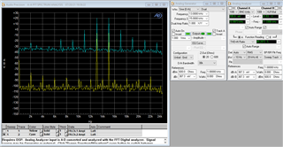
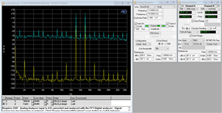
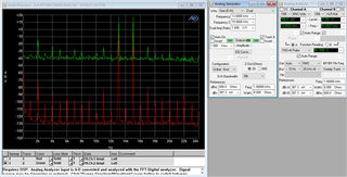
When I measure at INPUT_A / INPUT_B nets (on the TPA3255 side of the AC-coupling caps), the spectrum is showing significant IMD distortion tones:

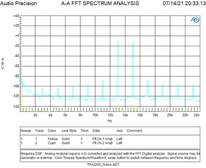
Now, I realize X7R as shown on the schematic snippet aren't ideal dielectric type.. the screenshot above shows the result after replacing X7R with 10000pF /C0G type. Since that didn't resolve the issue, I went ahead and air-wired in 6.8uF film caps in place of the 10000pF ceramic caps, but that didn't change the result at all.

Is there something inherent to the TPA3255 input that would cause these IMD products to appear? 

Does anyone have any other ideas about why this is happening and how to resolve it? 

Thanks!

  • Hi,

    As the differential test result showed no IMD tones, the output is also good, right?

    I think measuring the signals on input pins doesn't show any capability of the device... 

    Thanks!

    Regards,

    Sam

  • Sam,

    Let me clarify the graphs.. ignore ch1 in the above graphs, which are just loopback from AP tester output to input. Ch2 represents differential measurement between TPA_INPUT_A and TPA_INPUT_B, and then in the second graph, between INPUT_A and INPUT_B. 

    I can also confirm that the output of the TPA3255 also shows these IMD harmonics, indicating the IMD harmonics are present at the input of the device. 

    Thanks,
    Evan

  • Hi Evan,

    Understood. It still looks like something related to the passive components on input side... Any way, let me do some bench test on EVM and get back to you soon. Thanks!

    Regards,

    Sam

  • Sam,

    I just did some more testing on TPA3255 EVM instead of our hardware. EVM is configured for PBTL, so output filter is modified accordingly. 

    Differential FFT between C17/C28 (on op-amp side):

    Differential FFT between C17/C28 (on TPA3255 side):

    Can you reproduce this issue and explain the cause / fix?

  • Hi Evan,

    I just did some test on bench and noticed the result you got may be related to AP setting.

    Could you tell me your high pass filter setting on AP? I've noticed when using the DC, the result is similar to yours, while if using <10Hz AC, the result looked good.

    CH1: Input side

    CH2: Output side

    High pass filter: DC 

    High pass filter: <10Hz AC

    This result indicates when using DC, the AP input circuit is not working well. Could you try this on your side? Thanks!

    Regards,

    Sam

  • Sam,

    I am using a SYS-2722 which only has <10Hz AC option on the analyzer side. 

    I did notice something else interesting this morning, the spikes on INA/INB were not so pronounced as last week. I am not sure what the difference is. However, the IMD spikes are definitely still present on output of amplifier - can you please verify this?

    Also, with AP test probes between the INA/INB test points on bottom side of TPA3255 EVM, I noticed that the spikes increase quite a lot if you flick the TPA3255 RESET switch into reset mode, which tells me something about how TPA3255 is biasing or loading the opamp circuit.. 

    In case you're wondering why I'm concerned about this, it's because the customer is using the amplifier for encoded data transmission at low frequencies, not audio, thus additional IMD harmonics are a significant problem. 

  • Hi Evan,

    As you can see on the test result picture, I was measuring the J10 as input, and OUTA and OUTB as the output. If <10Hz AC was used, it didn't show many harmonics. The IMD is ~75dB.

    Could you try the similar test?

    Thanks!

    Regards,

    Sam

  • Sam,

    Yellow is J10, blue is OUTA/OUTB, with same measurement filters as you, so I think we can agree the results match pretty closely. However, my original tests were with 500mVrms input signal, whereas yours, and above are at 100mVrms.

    When I increase VIN to 500mVrms, the below IMD components are kicking in again. I am running PVDD=24VDC.

    If I increase VIN to 1Vrms, things look worse, as well as getting clipping indicator LED illuminated:

    However, increasing PVDD=48V, which removes the clipping indicator, does not remove the IMD components, but maybe reduces them down:

    It's interesting to note that these harmonics are present at the J10 connector, which I find strange. Just for sanity's sake, I did a straight loopback of AP generator to analyzer, and those IMD components are definitely not a product of the AP generator:

    I then tried changing R5 & R10 on EVK to 10kohm, to lower the INPUT_A/INPUT_B RC filter cutoff to ~160kHz without any appreciable reduction in IMD harmonics. 

    Conclusion, the input amplitude definitely is making a difference.. can you replicate these results on your end?

  • Hi Evan,

    Please see the test result with higher output level as below,

    In your result of 48V PVDD, 1Vrms input, it showed -40dB IMD. In my bench result, it looks better. I'm suspecting the AP2722 input sampling circuit is not good to handle the higher input level, rather than the device itself.

    Any thought, please let me know. Thanks!

    Regards,

    Sam

  • Sam,

    I repeated on a newer tester, seems the results match yours more closely. 

    I will check internally and see if perhaps the issue is just overdriving the inputs. 

    Thanks,
    Evan