This thread has been locked.

If you have a related question, please click the "Ask a related question" button in the top right corner. The newly created question will be automatically linked to this question.

TAS2563: EVM Dual Mono - shuts down - protection?

Part Number: TAS2563

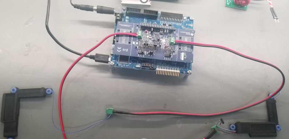
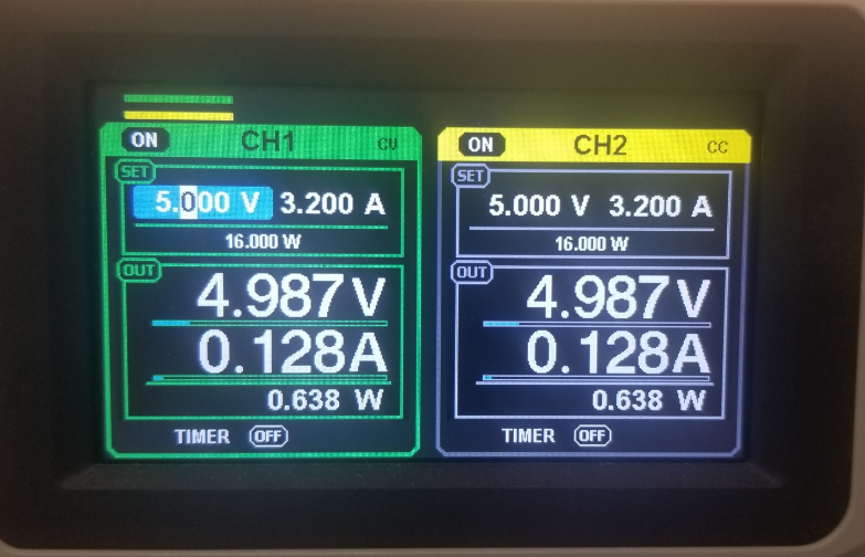
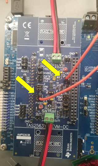
I have a TAS2563 stereo (dual mono) EVM powered by a lab supply 5V/6.4A to VBAT. I have been able to characterize the speakers. Works well with a single channel. The issue when I try to run a demo using two channels.

The setup is complete in PPC3, and music is passing through. When the volume form the PC is increased, the EVM will shutdown and the TI "soundcard" looses connection, the PPC3 does not identify the board. A power cycle and rebooting of the EVM resets the system to work again.

There is no indication of what is triggering the shutdown, is it in protection mode?

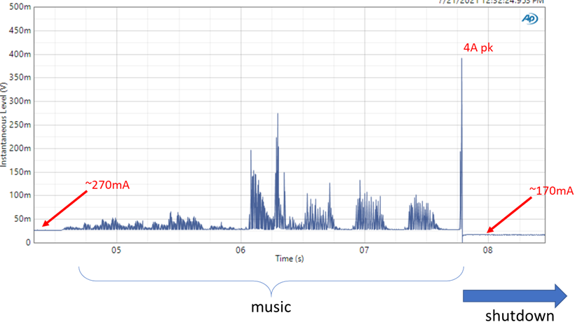
The system when on idle and ready to play has a quiescent current of 230~270mA

When the system shuts down, the quiescent current drops to ~150mA, there is no connection to the PC.

With the characterization board plugged or unplugged the behavior is the same, just different quiescent currents...

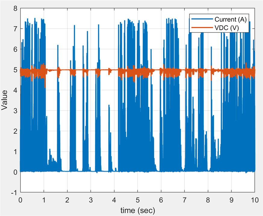
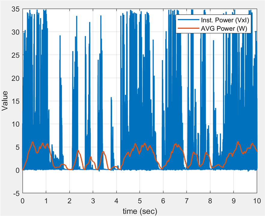
When I measure the current into the EVM using a 100mOhm shunt resistor, I see a peaks of about 4A prior to shutdown.

Questions:

(1) Should I expect the EVM to drive two 4ohm micro-speakers at max power (2x3W)??

(2) What is the protection mode that is triggered? how to debug?

  • Hi Mark,

    Would you be able to connect some bench supply directly to some jumper pins on the daughter card? I think the Motherboard supply input is not being able to handle the rising current of two channels.

    If you can connect the supply directly you can try the following:

    • Remove J1 and J10 on the daughtercard, this is VBAT supply.
    • Connect 5V supply to J1 on left-side pin and J10 right-side pin
    • Connect the rest of the setup the same as before and configure the devices.

    Please let me know if you have any further questions.

    Best regards,
    -Ivan Salazar
    Applications Engineer

  • Thanks for the response. Below is a picture of redirecting VBAT on the jumpers for reference.

    In order for the system to work, I split the supply VBAT for the power amplifiers and VBAT for the mother board (and characterization board).

    What I discovered, with the micro-speakers in the application I am using, I am seeing  7.5A peaks just on the amplifier side with VBAT of 5.0VDC. If we add the 5V for the rest of the system, is overloaded the lab supply resetting the TI EVM board.

    I measured the power supply voltage and current for this system and was surprised to see the peak currents (instantaneous power). The average power is very reasonable. See pictures below. 

    Questions:

    1) Is this expected behavior for this type of use case? It definitely helps define the power supply requirements!

    2) How to control the peak voltage at the transducer terminals (and hence the peak supply currents) if we need to reduce?

    Voltage, current measurements for micro-speakers playing music ("Another One Bites the Dust").

    The system is a 2x3W. The average power shows 5W peaks, so reasonable. The peak instantaneous power reaches 35W