This thread has been locked.

If you have a related question, please click the "Ask a related question" button in the top right corner. The newly created question will be automatically linked to this question.

OPA1642: Application in single power supply

Part Number: OPA1642
Other Parts Discussed in Thread: OPA1652, OPA1688

Dear,

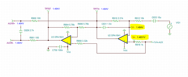
Is there a recommended application for OPA1642 working in +5V single power supply, is there any risk?  It seems below application not working properly, it on some units get terrible noisy output, also worse SNR and THD.

Thanks!

  • Hello,

    Both the OPA1652 and OPA1642 are specified at +/-2.25V split supply or 4.5V single supply as the minimum supply. Operating at 5V is sufficient. Have you tried swapping units to see if the problem follows the unit? On the units that exhibit higher noise and THD, do they appear damaged? Can they pass a signal?

  • Dear Chris,

    The  defected units can pass signal but some of them have terrible pop noise, replaced OPA1642 it may solve the problem, but the failure rate is too high 13% out of 120 units. The design was used OPA1652 that it goes OK in past production, the alternative OPA1642 due to OPA1652 is in shortage on market.

    With OPA1642 the 2V5 bias goes to pin3 and pin5 will drop to 2V3, does it seems normal? but with OPA1652 there is no voltage drops on 2V5  bias setting.

    Looking for your further comments, thanks!

  • Bolin,

    I am going to put this circuit in simulation to understand what may be happening. I see in the last schematic you shared that there is a set of  Amplifiers, U720-C, U721-C. Are you using a quad? How are those amplifiers configured? If they are not being used they should be configured into a buffer configuration with the output set to mid supply, so their outputs do not slam into the supply rails. They are currently hanging off of the circuit that forms the 2.5V reference for driving common mode of the other amplifiers. These amplifiers will demand up to 2.5mA of Iq per channel (5mA max) on start up and also slam into the rail if they are not driven with feedback. 

    Have you checked the 2V5DC Aux line for spikes and also noise?

  • Bolin,

    It looks like I missing some of the circuit on the front of U719A and B and how the input signals are connected. If you are seeing 2.3V at pin 3 then this indicates significant current. Can you check the 2.5V circuit for spikes and noise. There is excess current coming from somewhere if my red markers below are correct. Did I mark pin 3 with the correct voltage that you are measuring? This indicates 200uA and 60uA. The bias currents are below 20pA for the OPA1642 and 100pA for the OPA1652. You should not be seeing a significant voltage drop across those resistors. My suspicion is the 2.5V reference circuit providing the Vcm for these amps. This excess current of course would increase the noise. Please check all DC values, input and outputs to see if there is an issue in this path. 

  • Dear Chris,

    Sorry for confusion.

    The OPA1642 is dual, totally it used 7 for this application, what it showing part of them, U720-C,U721-C are the power supply for U720, U721.

    I am curious on the bias with OPA1642, the voltage tested on TP770 2V44, TP771 2V31, U720 pin1 2V3, pin7 2V9, U721 pin1 2V3, pin7 2V3, it very strange compared with applied OPA1652 which all the test point voltages are 2V48. Is the configuration should be different with OPA1642 compare to OPA1652?

    Thanks!

  • Dear Chris,

    Recheck on one unit, and tried some way to locate how the bias drops, it seems the bias was pull down by OPA1642.

                   Test Points
      Items

    TP770
    (V)

    TP771
    (V)

    U720

    U720

    U721

    U721

    Pin3

    Pin5

    Pin1

    Pin7

    Pin3

    Pin5

    Pin1

    Pin7

    Deault

    2.41

    2.29

    2.28

    2.28

    2.27

    2.27

    2.26

    2.26

    2.3

    2.3

    Remove R906, R907

    2.41

    2.29

    2.28

    2.28

    2.27

    2.27

    2.26

    2.26

    2.3

    2.3

    Remove R906, R907, R900-R903

    2.41

    2.29

    2.28

    2.28

    2.29

    2.29

    2.26

    2.26

    2.3

    2.29

  • Bolin,

    I have found the issue. I put a portion of your circuit into simulation and attached both simulations at the bottom of this post. 

    The OPA1642 has a common mode voltage range we specify to be Vcc-3.5V.

    OPA1642 Vcm Range:

    The OPA1652 Vcm range is Vcc-2V. 

    OPA1652 Vcm Range:

    You can see below that if I have 2.5V of common mode on the OPA1642 with a supply voltage of 5V then this violates the specified common mode voltage range and the inputs are pulled apart as shown with V- and V+ markers below. 

    Performing the same simulation with the OPA1652 the input common mode voltage range is not violated and the inputs are within a Vos apart. 

    If I take the common mode into the valid range for the OPA1642 then the inputs are no longer pulled apart as shown below. I accomplished this by changing resistor R808 to 1.4k. 

    The other approach is to increase the power supply. 

    OPA1642 vs OPA1652.zip

  • Dear Chris,

    Understood, thanks very much for you helping on this issue!

  • Dear Chris,

    Thanks for the recommendation, will have checking on it.

  • Bolin,

    No problem! If any of my answers were sufficient, it would help me if you could hit the resolved button best answer. Thank you!