This thread has been locked.

If you have a related question, please click the "Ask a related question" button in the top right corner. The newly created question will be automatically linked to this question.

LM4562: LM4562

Part Number: LM4562

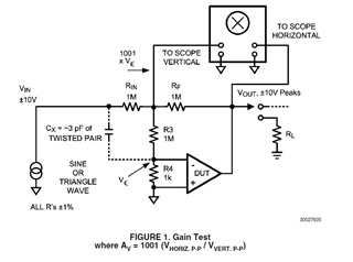
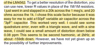
Hello. I have some doubts about the application note 1671 by Bob Pease. My question is not about how the test circuit from the app note works but how is he getting to the result of 0.08 ppm of distortion in his measurements, how did he actually get that result, are there any formulas he applied to the values shown in the crossplots? I ordered a few LM4562 opamps from TI and I want to perform the experiment from this app note. For what I undestand Bob Pease used plenty of crossplots to find out about harmonic distortion, he actually did a video in his show Analog by Design related to harmonic distortion measurement which can be found in TI’s youtube channel, but I have not found specific information related to the numeric methodology he employed. Could you help me with this particular subject?
  • Hi Jesus,

    This is a fairly old document, let me take a look at your questions and I'll get back to you during Tuesday or Wednesday this week.

    Best regards,
    -Ivan Salazar
    Applications Engineer

  • Hello, Ivan.

    Thank you for your reply and for taking the time to review my question.

    I look forward to your response.

    Regards.

    Andres.

  • Hi Jesus,

    The ppm value is based on the dB gain (or loss in this case) as compared to the signal level voltage, eg. for 7Vrms signal level, you get 1uVrms nonlinearity, that means ~137dB; now just a reminder that 1% is 1/100 and similarly 1ppm is 1/1000000 = 1e-6, then our example of 137dB would be 1.41254e-7 or 0.141254ppm.

    Hopefully this helps, let me know if you have any specific questions.

    Best regards,
    -Ivan Salazar
    Applications Engineer

  • Hello, Ivan, thank you for your reply.

    I think I solved it.

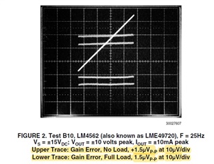
    According to Bob’s measurements from figure 2, we obtain the following:

    The gain error both with and without load is equal to 1.5uVpp or 5.3E-07 Vrms.

    Now, if we divide this error between the output signal, we’ll get the lowest value for the distortion or the system nonlinearity:

    Distortion = 5.3E-07Vrms/7.07 Vrms = 7.5E-08 or  ~8E-08, which can be stated as 8E-08*1E06 = 0.08 ppm.

    Therefore:

    20log(7.07) = 16.98 dB

    20log(8E-08) = -141.93 dB

    This means that this particular op amp (LM4562 according to the data in the crossplot) has a distortion of -141.93dB – 16.98dB = -158.91 dB ~ -159 dB @ 25Hz  with respect to the reference signal, exactly as noted by Bob Pease in the text.

    Regards.

    Andres Sanchez.

  • Hi Jesus,

    This seems correct, thank you for coming back and sharing this for the community.

    Best regards,
    -Ivan Salazar
    Applications Engineer