Because of the holidays, TI E2E™ design support forum responses will be delayed from Dec. 25 through Jan. 2. Thank you for your patience.

This thread has been locked.

If you have a related question, please click the "Ask a related question" button in the top right corner. The newly created question will be automatically linked to this question.

PCM4204EVM: Differential amplifier from input side

Part Number: PCM4204EVM
Other Parts Discussed in Thread: PCM4204, OPA1632, NE5532

Dear team 

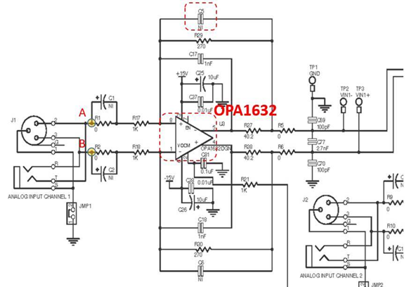
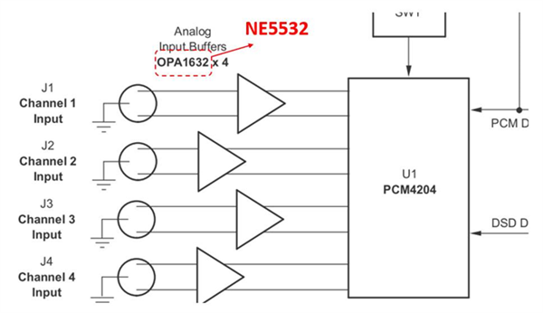
On the PCM4204 EVM board, use OPA1632 on the Input side, as shown in the figure as below from user guide page 6.

1. Can NE5532 replace OPA1632?

2. What is the difference in application between NE5532 and OPA1632?
Many thanks

Denny

  • Hello Denny,

    THE NE5532 seems to be somewhat less sophisticated whereas OPA1632 is specifically for audio use and maintains a good THD+N level whereas for the other part I could not say how it could affect the overall THD+N of the system.

    Best Regards,

    Carson

    Low Power Audio Apps Engineer

  • Hi Allen

    OPA1632 is the OPA of Differential Input Differential Output.

    1. Whether the signal source of the two points A/B in the figure is a single end or a differential? Because generally if the signal is connected by the Phone Jack, the signal source should be the left channel and the right channel of the single end. If  want to connect a differential signal, how to connect without a differential signal?

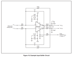
    From datasheet page 17.

    2. The C5 component is no connect, is there a recommended value of capacitance and the size is reserved for use?

    Many thanks

    Denny

  • Point A and Point B are differential input. If you want single ended you would ground negative input to OPA but full scale would be split in half as you would only be able to max out at 3Vpp on other side of buffer.

    The device is meant to accept balanced TRS signal or XLM connection in configuration

    I would ignore capacitors as in applications section of non-EVM datasheet for part shows this 

    Best Regards,

    Carson

  • Hi Allen

    AS your feedback: ”The device is meant to accept balanced TRS signal or XLM connection in configuration”.

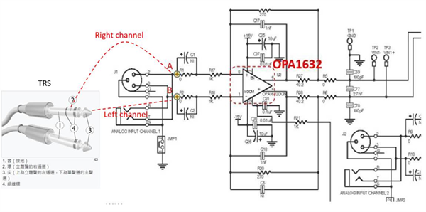
    I would like to know, The TRS signal are similar single end signal, It have Right/Left channel.

    1. May I used Right channel connect to point A and Left channel connect to point B?
    2. Case 1, point A and point B connect to single end signal.   
    3. Case 2. Point A connect to single end signal and point B connect to GND. What is the difference between case 1 and case 2?

    Many thanks

    Denny

  • Hello,

    No you would need to use them like they should and connect them to different channels so that in the output I2S you would have left and right channel output. You can only connect 1 TRS to one channel.

    Are you trying to use 2 TRS pins to turn stereo into mono?

    Best Regards,

    Carson