This thread has been locked.

If you have a related question, please click the "Ask a related question" button in the top right corner. The newly created question will be automatically linked to this question.

TPA3221: Output filter

Part Number: TPA3221

Hi there

So I'm designing an output filter for the TPA3221 in stereo mode (2x 3ohm load) but having trouble selecting the right inductor. The recommended inductors are:

Coilcraft UA8014-AL

Sagami 7G14J-100M-R / 7G14D-100M-R

However, the availability of the Sagami is poor and the price of the Coilcraft is very high. So I'm looking for alternatives in small form factors.

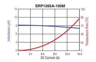
Would Bournes  SRP1265A-100M work ok? The inductance/current curve is fairly flat from 0 to 9A.  

Are there any other inductors you can recommend?

Second question:

Originally I was using a 6.8uH + 068uF LC filter as in the TPA3220-MICROEVM. However, this wasn't giving me good results in radiated emissions EMC testing. So I'm going to move to 10uH. 

1) What capacitor should I use for 3-ohm load for best EMC results? 1uF? 1.5uF? 2uF? How will this affect idle losses?

2) On the datasheet/evm there are additional filter components: 10nF+3.3r and 1nF. Will these help with EMC?

3) On the datasheet for the TPA3221 is says to use 10nF+3.3r and 1nF but on the schematic for the EVM it says 1uF+3.3r and 1nF. Which is best to use!?

Third question:

Any other tips for improving EMC? I'm already using a 4-layer board, placing the decoupling 1uF caps really close and running the switching outputs on an internal layer.

Thanks

  • Hello David,

    Question 1:  from current rating aspect, i see no problem using this inductor from Bourns. But you still need to test THD performance to confirm if meet requirement.

    Question 2: what frequency failed radiated emission test?  If low freq, then an aggressive LC filter probably works. If high frequency, then LC may will not work if out of component's SRF range.  

    1) A good suggestion is test them in chamber. 

    2) These are not used on EVM, just a placeholder there. 

    3) please refer to datasheet 10nF+3.3r.  EVM is just a placeholder there.

    Question 3: EMC is a system problem, should be case by case analysis.  may you provide below information. then some furthur experiment is required to find where is the root cause.

    1. pictures of PCB, chassis

    2. what power supply used?

    3. EMC test plot

    Dylan

  • Thanks Dylan

    I don't have the equipment to measure the THD really, I was hoping for an opinion based on the LC curve I posted. However, the reality is that I don't think the difference between 0.01 and 0.1% THD would be audible. 

    Chamber time is expensive so I don't have hours of time to do multiple tests and play around with changing components... I was just hoping for generic advice really. 

    My final question is regarding the R-C snubber. A 1uF+3.3r would be there to dampen the filter's resonant peak which should be recommended? What is the purpose of a 10nF+3.3r?

    Regarding EMC I would like to speak privately about this so I can share pictures and plots. Can I arrange this? 

    David

  • Hello Dylan,

    The 10nF and 3.3r is is called "zobel network". It's used to dump the impedance peak(vs. freq) of a real speaker model. If you are using a known impedance load, then just remove it.

    best regards,

    Luis