Other Parts Discussed in Thread: PCM5142, SRC4392,
DAC team,
Our customer is trying to get a THD+N reading similar to the datasheet. They get -91.5 dB on the left channel which they can accept, but the right channel is at about -90 dB. Maybe it's a matter of setup, so I asked for details about the test setup, which I'll list below.
Please let me know what you recommend.
There are just 3 cables:
- Audio Precision APx525 Optical out -> PCM5122EVM Opto SPDIF in
- PCM5122EVM OUTR (or OUTL) -> APx525 Analog Input 1 (Unbalanced) using RCA cable (~1m) and an RCA-BNC adapter
- USB connection to my laptop docking station for power and control
The laptop is in a docking station and AC powered.
See images in the .7z file attached.
Configuration notes:
- Jumper W5 on pins 2&3 to select RXCKO
- Configure SW3 as HHLX (A-D) – MCLK #4, 24.576MHz from Osc Y2
- Use PurePath Console v1.16 and select PCM5142 EVM
- Use Direct I2C Access to load and execute “Optical/SPDIF Input via J4 (48 kHz, RXCKO Master Clock)” script from EVM user guide (section 2.5.3)
- Script file I use attached here as PCM5121EVM_SRC4392.txt (copy/paste from EVM user guide)
Everything else is default.
Observations (quoting the customer):
- To get better than -91dB THD+N on the “good” EVM channel OUTL, I had to disable the PLL in the PCM5122, and mute the Audio Precision digital output channel associated with the EVM OUTR
- Seems like there is a bit of crosstalk on the EVM somehow? Improvement in THD+N by muting the input associated with OUTR was ~1dB at 1kHz
- OUTR THD+N performance was NOT noticeably improved by turning off the OUTL input
- OUTR as is doesn’t meet the -90dB THD+N target
He saw a small improvement (~0.2dB) in the THD+N performance on both channels when he disabled the PLL in the PCM5122 (cleared bit 0, register 4, page 0).
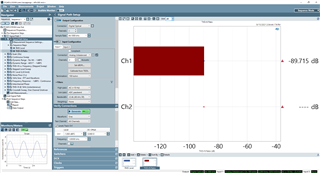
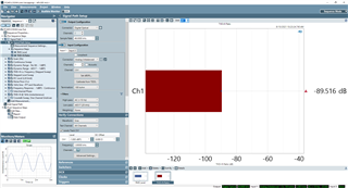
OUTR THD+N measurement (1kHz, -1dBFS, High Pass filter = AC (10Hz), Low Pass filter = AES17)
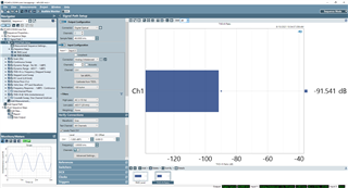
OUTL THD+N measurement (1kHz, -1dBFS, High Pass filter = AC (10Hz), Low Pass filter = AES17)
Clocks are:
TP13 LRCK = 48.00kHz
TP11 BCK = ~3.072MHz
TP10 SCK = ~24.576MHz
Register settings:
# RESET RESET THIS IS MASTER RESET FOR SRC
# SW3 (2-7) turned on, rest turned off
# Page 0 = DEFAULT for Control
# Write to page 0
w E0 7F 00
# Register 01, Bit 7 = 1 resets to default
d 100
w E0 01 80
# Delay 0.1 sec to allow part to reset
d 100
# Register 01, Bit 7 = 0 for normal operation
w E0 01 00
d 100
# w E0 7F 00
# Register 01, Bit 7 = 1 resets to default
#----- Setup Port A ------#
# 24bit I2S, Master mode, DIR source, at mute
# Divide by 256, MCLK input source
w E0 03 69
w E0 04 0B
#----- Setup DIR ------#
#DIR Config 1
# Input source: RX2 - S/PDIF RCA (default)
#w E0 0D 01
# Input source: RX4 - S/PDIF optical, RX_MUX = RX1
w E0 0D 08
#DIR Config 2 - default
w E0 0E 01
#----- Setup DIT -----#
# DIT COnfig 1
# Port A data in, DIv 256
w E0 07 80
# DIT Config 2
# Default is to output to RCA
# Commment out RCA and uncomment Optical for optical outputs
#Output to RCA
# TX - ON, TX MUTE - ON, Optical disabled
#w E0 08 06
# TX Mute - OFF
#w E0 08 04
#Output to Optical
# TX - OFF, TX MUTE - ON, optical disabled
w E0 08 03
# TX MUTE - OFF
w E0 08 01
#----- PLL Configuration -----#
# Set P=2, J=8, D=0
w E0 0F 22
w E0 10 1B
w E0 11 A3
# GPIO1 Config
# GPIO1 = RCVR non-audio data
w E0 1B 06
# GPIO2 Config
# GPIO2 = RCVR non-valid data
w E0 1C 07
# Power Status
# Disable RCVR (/PDRX) and Port B(/PDPB) power down and enable All Function power down
#w E0 01 14
# Unmute Port A Output
w E0 03 29
# Disable All Function power down (all blocks set by local control)
w E0 01 3F
Thanks,
Darren