Because of the Thanksgiving holiday in the U.S., TI E2E™ design support forum responses may be delayed from November 25 through December 2. Thank you for your patience.

This thread has been locked.

If you have a related question, please click the "Ask a related question" button in the top right corner. The newly created question will be automatically linked to this question.

PCM1681: PCM

Part Number: PCM1681
Other Parts Discussed in Thread: TL074

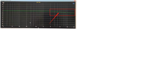
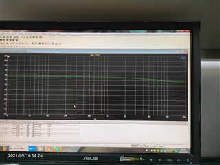
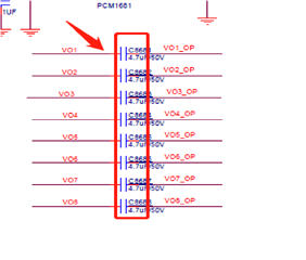
     The PCM1681 output  power amplifier should be a horizontal line without EQ, but we found that the output line of the PCM1681 was very serious between 2K and 20K,  12W for a single channel, we made up for this defect through the software. Now the output power is 70W, but the sound effect is very poor after the software made up. The EQ free curve of the output of PCM1681 and schematic diagram.

PCM1681电路.pdf

  •  Do you mean via software you made the curve flat? can you tell us what  you did through the software? Also what is the y-axis on the plot , I can not see the numbers very well.

    I need to check the schematic first and then review the issue. 

    Thanks.

  • Adjust the high-frequency EQ through DSP simulation software to flatten the falling curve. The y-axis is the output gain, its size is synchronized with the volume.

  • Hi, Could you please confirm where are you measuring the frequency response? Is it directly at the output of the PCM1681 or after the TL074 op amps?
    The RC at the input of the TL074 has a cutoff frequency of ~3.4kHz (10k-Ohm + 4.7nF), which may explain the attenuation you're seeing at higher frequencies.

    Best regards,
    -Ivan Salazar
    Applications Engineer

  • Disconnect PCM1681 output capacitor, The test network is VO1~VO8 network.

  • Hi,

    Could you please confirm that you removed the capacitors from your capture and measured directly at the output of the PCM device? It was not clear from the statement above.

    I'm also wondering why is there a level of less than -10dB before the roll-off, can you try the same test at full-scale? It should be 0dB. Please comment on the following:

    • What is your input signal during the test? Are you sending 0dBFS from AP and sweeping over frequency?

    Best regards,
    -Ivan Salazar
    Applications Engineer