This thread has been locked.

If you have a related question, please click the "Ask a related question" button in the top right corner. The newly created question will be automatically linked to this question.

TLV320AIC3110: Power and I2C communication sequence review

Part Number: TLV320AIC3110

Hi Sir,
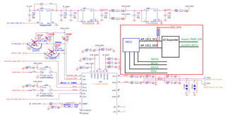
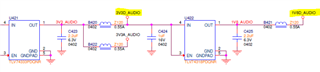
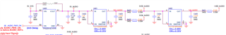
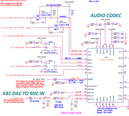
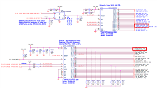
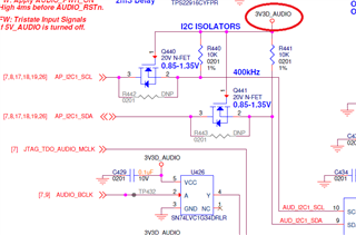
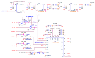
Good morning. Please help to review the following circuit.
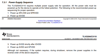
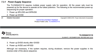
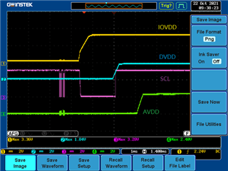
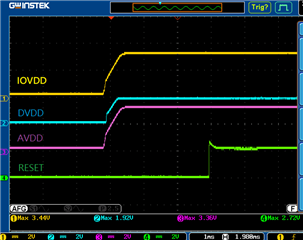
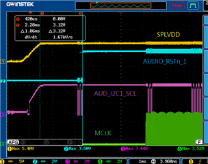
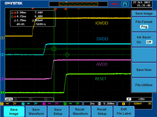
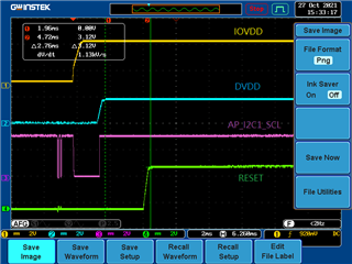
Does any concern about the power-on sequence and I2C communication sequence during power on stage?
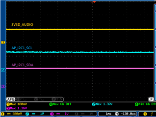
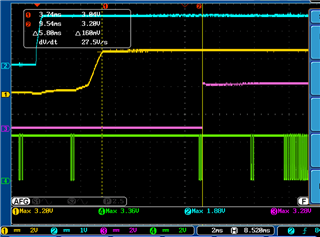
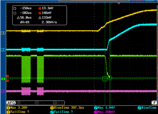
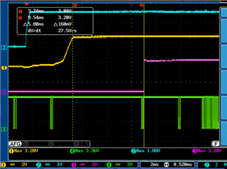
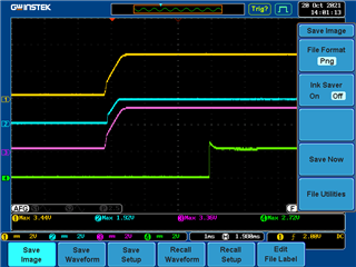
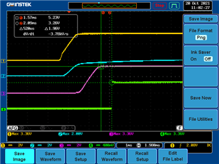
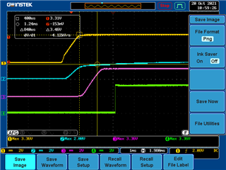
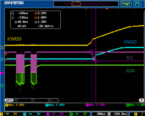
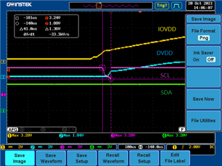
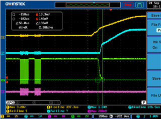
Some boards have abnormal symptoms(initialize stage) after Codec power on stage, which is I2C Clock assert a short time to low level at 1.8V power-on, then the I2C bus got stuck at a high level(3.3V),
and the Host's I2C bus doesn't work normal anymore.

Ch1 -> 3V3D_AUDIO

Ch2-> 1V8D_AUDIO

Ch4-> I2C1_SCL

Regards,

Joseph 

  • Hi Joseph,

    I don't understand by the comment "after Codec power on stage, which is I2C Clock assert a short time to low level at 1.8V".

    Are you saying that the host will pull SCL low for a short time to 1.8V to power up codec?

    I'd suggest change R440 from 10K to say 2.2K for fast mode and populate R442 with 0 Ohm and check if you see the issue.

    I'm not sure I understand the scope capture prior to that small dip.

    On Channel 4 (I2C1-SCL) are those I2C transaction at 3.3V even though 3V3D_AUDIO is low?

    Regards.

  • Hi Pdjuandi,
    Thanks for your timely response.
    I don't think it's the host that pulling the clock low, it looks like the clock stretching by the slave. We did populate R442 with 0ohm and saw the same phenomenon. I believe the pull-up resistor is another issue apart from this topic, although we need to change pull-up to 2.2K for more driving current depends on parasitic capacitance on the trace.
    On Channel 4 (I2C1-SCL) are those I2C transactions at 3.3V even though 3V3D_AUDIO is low?
    -> Yes, before the 3V3D_AUDIO assert to high the host I2C communicate with the I/O expander to control the AUDIO_PWR_ON assert to high level

    Regards,
    Joseph

  • Hi Joseph,

    I see, so the host has its pullup to communicate with the IO expander. Why do they need another pull up here to 3v3d_audio?

    The dip is because the device pull up is not ready yet from U421 while the host has its pull up already at 3.3V.

    Why the dip causes the host to stop working, is it not supporting clock stretching?

    Can they try remove this device pull up and just use this host pull up? 

    Regards.

  • Hi Pdjuandi,

    Thanks for your reply.

    1st Experiment.

    We have tried to remove the device PU and Mosfet, install a jumper on R442 & R443 .(as the following figure).

    For the codec's control signals please refer to the red block diagram.

    The power-on sequence of the circuit is 5V_SYS -> 3V3_SYS -> AUDIO_PWR_ON(5V_AUDIO,3V3D_AUDIO,3V3A_AUDIO) -> 1V8D_AUDIO

    Under this situation, the I2C bus still stopped working and the I2C voltage level became 1.36V and also affect the IO expander working normally.

    2nd Experiment.

    Changed 3V3D_AUDIO,3V3A_AUDIO to 3V3_SYS.

    The power-on sequence becomes 5V_SYS -> 3V3_SYS,3V3D_AUDIO,3V3A_AUDIO -> 1V8D_AUDIO

    Under this situation, the I2C transaction working normally with the device.

    So, for the Codec power-on and I2C communication sequence portion. Does it mean Codec's power(3V3) is simultaneous with the I2C host PU?

    or Can we wait for the all codec's power ready then I2C communication after( used Mosfet to block host I2C signal)?

    Regards,

    Joseph

  • Hi Joseph,

    We need CODEC power IOVDD, DVDD to be ready and with reset pin pulled low will put the device in a known state as described in the datasheet below.

    Can you try using the original setup but this time pull codec reset low for at least 10ns?

    Regards.

  • Hi Pdjuandi,

    We have tried Codec's power-on and I2C transaction sequence like the following figure1 that is successfull condition, but that still occurs failure chance on this sequence as figure2. Once I2C_CLK is stuck at a failure moment the host I2C doesn't workable anymore also can't control the IO Expander to release AUDIO_RSTn.

    CH1 -> 3V3D_AUDIO,3V3A_AUDIO

    CH2 -> 1V8D_AUDIO

    CH3 -> AUDIO_RSTn

    (Figure1)   

     (Figure2)

    Regards,

    Jospeh

  • Hi Joseph,

    In Figure 1, why 1V8D_Audio comes up before 3V3D-Audio?  Is this not current schematic?

    I would expect IOVDD (3V3D_AUDIO) to come up first then DVDD (1V8D_AUDIO).

    Once these supplies are up, you pull reset low for at least 10ns.

    Below the power supply sequence from datasheet:

    Regards.

  • Hi Joseph,

    So are you able to provide IOVDD, DVDD then pull reset Low for at least 10ns?

    Regards.

  • Hi pdjuandi,

    This is Lex Hsiao, Joseph's associate.

    Sorry to delay so many days to answer your question.

    First of all, the sequence in Figure 1 is the modified circuit using extra wires just for the experiment purpose, we try to comply with the recommended sequencing which is AVDD ramps up at the latest. We notice that by this action, it appeared to dial down the failure rate a bit, but still failed from time to time.

    And about the proposal you made, to pull reset LOW for at least 10ns, I believe the reset signal in our schematic did remain LOW around 5.8ms in all our experiments.

    I would like to address other questions to you for the explanation, if I may.

    1. I went through all the comments from this thread and I found one interesting comment is that “The dip is because the device pull up is not ready yet from U421 while the host has its pull up already at 3.3V.”. I think it suggests we should power up through each pull-up resistor at the same time on both sides of NMOS. It’s a bit strange because if we have to accomplish this, we need to power up AIC3110’s power at the beginning of our system. Could you comment on this?
    2. This drop only on the SCL line, we thought it’s a clock stretching mechanism at first, but clock stretching should only happen during data transfer. My guess is, the open drain inside the AIC3110 on the SCL pin is shortly turned on during the AIC3110 power-on sequence, so the SCL has been pulled to a low level temporarily, and the MCU somehow believes that the slave is not ready to communicate. If so, maybe we need to enlarge the capacitance on the IOVDD to make a soft-start, but I’m not confident to solve this issue only by adding more capacitors to it.
  • Hi Lex,

    1. The codec requires the IOVDD, DVDD, AVDD to be up with reset pulled low for at least 10ns to ensure the digital block are at a known state. When these supplies are not up, the codec digital node is in undefined state. That's what I'm referring to in that comment. So we need the power sequence as specified in data sheet to avoid case like this.

    2. This is not clock stretching. As mentioned above when these supplies are not up, the digital node is in undefined state and there is possibility being driven low during supply ramp-up phase however soon after the power-sequence completion (which ensures digital core reset), the device is expected to drive SCL and SDA HiZ.

    Regards,

    Peter

  • Hi Peter,

    I agree with you that the digital node is in an undefined state before all power supplies are ramp-up. And for the RESET signal, we did make sure it stays LOW over 5ms before it goes HIGH. Actually, we already tried to jump wires to wires to make sure we stick to the power-up sequence recommended in the datasheet, but the symptom still existed. Once it happened, it will cause the HOST to be tied up, and the whole system is halted.

     Let's bring up the following topic for further discussion.

    1. The SCL being driven LOW during power-up EVEN THOUGH we followed the power-up sequence and RESET remained LOW more than 10ns. So we believe this symptom is not related to the sequencing.

    2. We just find out this symptom can be reproduced very easily under high-temperature conditions, about 50-degrees Celsius. And we observed that if SCL dropped under 1.64V, it will cause the system to halt.

    Could you help to provide any other possible solution?

    Thanks

  • Hi Lex,

    We never see a case where all supplies are up and reset has been applied yet a glitch on SCL line, we need to investigate further.

    Can you provide the scope capture for IOVDD, DVDD, SCL and RESETZ as a start when this happens? If you can have more channels in your capture then add AVDD and SDA for completeness. In this debug we want to make sure host is not driving or initiate any transaction. The I2C lines should already be HiZ when power sequence is complete. 

    Regards,

    Peter

  • Hi Peter,

    We have tried to modify the power rail circuit by manual trying to meet the power-on flow Spec. requirement.

    The SCL line glitch to low symptom is gone under the room temperature turn-on test but still occurs on the high-temperature turn-on test 80C. The SCL will gitch to low under 0.6V.

     I'm not sure the time between every power rail is enough, or not?

    Does any suggestion for a specified delay time between these power rails? Would you please advise on this?

    (Original Design Power-on sequence)

    Ch1: 3V3D_AUDIO

    Ch2: 1V8D_AUDIO

    Ch3: 3V3A_AUDIO

    Ch4: AUDIO_RSTn

    (Note: There is a problem with the Ch4 probe, the voltage should be 3.3V after changing a good one.)

    To adjust TLV320AIC3110 power-on sequence

    SCL glitch to low under high-temperature turn-on test

    Ch1: 3V3D_AUDIO

    Ch2: 1V8D_AUDIO

    Ch3: SCL

    Ch4: SDA

    Regards,

    Joseph

  • Hi Joseph,

    The datasheet power sequencing does not have specific timing only the order.

    It looks like you have that in your room temp scope capture and it works as expected.

    At high temp, this SCL glitch is happening when the IOVDD and DVDD are not fully powered.

    These powers need to be fully up then after at least 10ns release reset to high.

    Regards,

    Peter

  • Hi Peter,

    I'd like to update some information for your reference.

    I increased the time interval between each power rails to see if this phenomenon still happened under high temperatures, and here is the result.

    (The AVDD Max. voltage only shows 2.4V is caused by the un-calibrated probe)

    You can see the issue still there even we follow the power-up sequence as the datasheet recommended.

    Could you help to advise the next step?

    Thanks

  • Hi Lex,

    The issue is the DVDD supply is not powered up. The requirement is shown below in the datasheet.

    You need to bring these supplies fully powered up then you can release the reset pin and the part will be in a defined state.

    Regards,

    Peter

  • Hi Peter,

    Sorry, I don’t understand why you’re saying the DVDD doesn’t power up?

    The picture I posted has the DVDD POWER UP TO 1.84V. I post again below. All power supplies are powered up. Please ignore the probe 4 measured number, it should be 3.3V, not 2.4V because probe 4 is un-calibrated.

  • Hi Lex,

    As you can see glitch on SCL occurs when DVDD is still low, when all powers are up sometime on the right side of the capture do you release the reset pin?

    The I2C pin will be HiZ once reset is released to high after at least 10ns. I don't see the reset pin on this capture.

    Regards,

    Peter

  • Hi Peter,

    I would like to sort up all the situation because it's getting blurred so far.

    1. Schematic:

        Power


        Audio Codec


        IO expander


        The AUDIO_PWR_ON and AUDIO_RSTn are controlled by the IO expander.

        IO expander's I2C and Audio's I2C are connected together to the CPU.

    2. First of all, the original design is to power up all the supplies at the same time, and the RESET is released to HIGH after sending the AUDIO_PWR_ON(SPLVDD) signal about 2ms.

    3. The issue is that we found sometimes the speaker that connects to the Audio Codec has no sound heard. So we measured the I2C signal and found that the issue happened while the SCL has a drop on it. And this drop became even worse under high temperatures. And when this drop existed and was lower than1.64V, the I2C bus was halted and couldn't work anymore. That means we couldn't command the IO expander to send out the RESET(AUDIO_RSTn) signal, so the RESET can never be released to HIGH.

    25 degree-C (SCL drops to 1.8V)                                                            

    56 degree-C (SCL drops to 0.48V)

    4. We tried to make a delay between each power rail, and it was clear that the SCL had been pulled to LOW while the IOVDD went up, and recovered to HIGH while DVDD jumped in. And for sure that the RESET couldn't be released to HIGH due to the glitch on SCL.

    I think it's quite clear that this glitch is caused by IOVDD, and I'm having trouble believing that the RESET is relevant to this issue since the SCL is pulled LOW during the power-up sequencing. I understand that the I2C only be HiZ after the RESET is released.

    Could you help to explain why the SCL has been pulled to LOW when the IOVDD is up?

    Thank you.

  • Hi Lex,

    As mentioned above, when IOVDD and DVDD are not fully up the digital core is in undefined state and it needs to be up and reset transition from low to high to bring it to a defined state which in the I2C case be in HiZ state as mentioned in the datasheet reset section above.

    When the digital core is in undefined state, it could be driven low as seen here.

    You will need to bring these supplies to fully up and release reset from its low state to high so I2C lines can be in its HiZ state.  

    You could try isolating your reset pin from its current connection and pull low when you are powering your supplies and once the supplies are up change it to high.

    Regards,

    Peter

  • Hi Peter,

    Instead of being controlled by the IO expander, I try to pull the RESET to HIGH using another method, and here is the result.

    As above scope shots, even the RESET pin can be released to HIGH successfully, but still, the I2C bus is halted by the codec.

    The CPU still can't control the I2C bus ever since, so I think the RESET is not relevant to this issue.

    When the digital core is in undefined state, it could be driven low as seen here.

    May I ask if this symptom applies to every codec product from TI?

    Because this is the first time I saw this phenomenon.

    If the SCL has the chance to be pulled to LOW before RESET is released, I think the best way to solve this issue is, change the power source at the gate of NMOS to AVDD, which is the latest one from the power-up sequence, to make sure the I2C bus from the CPU only conducts to the codec after the codec's power supplies all set.

    Thank you, Peter, for so much help and patience.

  • Hi Lex,

    Only a few old devices like this one has this requirement.

    Have you changed the pullup value and ensure that nothing is preventing it to pullup to IOVDD?

    This low level on SCL does not look like a glitch but more like something is holding it low.

    I'd expect the I2C would be HiZ if supplies are up and reset transitioned to high.

    Try changing the gate voltage or even bypass it for now to ensure I2C lines are HiZ.

    No worries, we are here to help.

    Regards,

    Peter

  • Hi Peter,

    May I ask what would you advise we change to which part number in the future can replace the one we're using now without modifying the layout?

    We did change the pull-up value to lower resistance, but still the same.

    And we tried to cut out I2C from the codec, and the symptom was gone.

    For the short-term, we can only turn the audio power supplies on along with the system power at the beginning and scrap the idea to put the codec into sleep.

    Because we don't have extra GPIO that can control the sequence, nor extra power to supply the I2C NMOS.

    Thanks

  • Hi Lex,

    Attached here is a high level summary of some of our codec devices, this is by no means exhaustive.

    AIC-PCM products_scale.pdf

    For the full list you can look under this link which is only sorted for audio codec.

    https://www.ti.com/audio-ic/converters/codec/products.html

    OK. I will close this case then.

    Regards,

    Peter