This thread has been locked.

If you have a related question, please click the "Ask a related question" button in the top right corner. The newly created question will be automatically linked to this question.

TAS2559: Configuration Programming for Baremetal Application on Custom Hardware

Part Number: TAS2559
Other Parts Discussed in Thread: , TAS2560, TAS2563

Hello,

I'd like to follow up on my previous post from a few months ago regarding using the TAS2559 in an embedded environment. Our hardware has arrived and I am trying to bring up the TAS2559 using the configuration sequence generated by PurePath Console 3 and the Python script you provided, but I am entirely unable to get the speaker to produce sound.

We are using an STM32 chip to program and enable the TAS2559 in a baremetal environment. I am currently using MCLK = 4.096MHz and BCLK = 1.28MHz hoping to support 16kHz 16-bit mono audio in Mono PCM Mode. To achieve this, I have set the audio frame length to 80 bits, as this triggers a pulse on the word clock at a rate of 16kHz. I can verify that these signals are being generated properly using a scope.

The configuration I am using immediately enables the speaker on the TAS2559EVM eval board with no additional configuration required. On our hardware, I have taken the following additional steps after programming the TAS2559 using the generated header file:

  • Wrote 0x01 to register 0x22 DSP_MODE to manually set the chip to Smart Amp mode
  • Set bits 1 and 2 in register 0x2A ASI_CTRL_1 to configure ASI1 to use monoPCM
  • Wrote 0x01 to register 0x2F ASI_CTRL_2 to denote 16kHz sampling rate in PCM mode
  • Set bit 7 in register 0x01 ASI1_FORMAT on page 1 to set the ASI1 input mode format to MonoPCM.

And I have also tried manually setting the following hardware configuration registers to match our hardware pinout, though all of the values programmed are listed as preferred: ASI1_BCLK, ASI1_WCLK, ASI1_DIN_DOUT, GPIO2_PIN, GPIO4_PIN, GPI_PIN.

Still nothing sounds. 

All of the power lines on our board are as specified and within tolerance. I have checked all of the documented status registers. Everything is powered on and nothing reports any voltage, current, or clocking errors. We are programming the TAS2559 using an I2C bus and all of the writes are ACKed, and I can correctly read back written register values, so I believe that the chip is receiving its program correctly. I have even tried running the device in ROM mode 1 (PCM input playback only) just to get some sort of sound out of the device but nothing works. Is there anything I'm missing?


Some additional information: When I could not get the evaluation board to produce sound in my last post, the issue was a clocking mismatch. Here I am sure that I have correctly configured the chip to expect 4.196MHz from MCLK. Is it possible that either BCLK or WCLK are causing issues? None of the clock values selected are set in stone, though BCLK and the frame length are selected to configure a 16kHz WCLK. Perhaps it's also possible that the 80-bit frame length is causing data issues? The documentation specifies that the rising edge of the word clock denotes the (n-1)th data bit, but we are sending 16 data bits in the first 16 clock cycles of an 80-bit frame. I expect the remaining 64 bits in the frame to be ignored; is this the case? 

I have attached the configuration file and its generated C header file as well.


Thanks, 

Sam 

parse.cfgaudio_config_generated.h

  • Hi Sam,

    I'll check your descriptions and come back with further comments within today.

    Best regards,
    -Ivan Salazar
    Applications Engineer

  • Sam,

    I don't think the expectation of the device to ignore the additional bits is correct. The data coming into ASI input should be based on format standard. I can try your cfg with a similar setup using AP as digital input, could you please confirm/comment on the below:

    • MCLK = 4.196MHz is not a selectable option at End System Integration, perhaps it is 4.096MHz?
    • BCLK = ??
    • WCLK = 16kHz

    Best regards,
    -Ivan Salazar
    Applications Engineer

  • MCLK indeed is 4.096MHz, my bad. The 4.196 is a mistype.  

    BCLK = 1.28MHz. 

    A more comprehensive description of how the monoPCM mode works for this chip would be greatly appreciated, especially if you suspect that having additional bits per sample may be the culprit of this issue.

    Per the documentation, "In mono PCM mode, the rising edge of the word clock starts the data transfer of the single channel of data. Each data bit is valid on the falling edge of the bit clock." The example given in Figure 39 in the documentation confirms this. We are using an 80-bit data frame for a 16-bit sample - this allows us to match a 16kHz WCLK with the master clock division provided to us by the STM platform. If we have to have precisely 16 bits in our mono PCM frame, we may run into issues, as the STM clock division is not flexible enough for this configuration. The TAS2559 documentation does not state anything about the frame size. Is having additional dead bits in a frame an issue?

    Maybe we can try using the TAS2559 ASI_OFFSET1 register to push the significant data bits further back in the frame? I tried that in my earlier debugging and it did not produce any sound, but maybe I made a mistake somewhere. 

    Thanks, 

    Sam 

  • Hi Sam,

    Thanks for feedback, I'll get it setup for your clock settings and will let you know the results.
    I'll also check your further description above.

    Best regards,
    -Ivan Salazar
    Applications Engineer

  • Hi Sam,

    I've been testing an EVM with similar setup, let me comment on the test details below, also attached are the configuration files I'm using:

    • Audio source is set to:
      • MCLK = 4.096MHz
      • BCLK = 1.28MHz
      • WCLK = 16kHz
      • 4 channels
      • 16 bits data
      • 20 bits/channel
      • WCLK bit-wide pulse (1 bit instead of 50-50 square wave)
      • 1-bit offset
      • Left-justified
    • I had to use these settings for 80 bit WCLK to BCLK ratio = 80, however as long as data is coming on the first 16 bits it should work the same.
    • End System Integration is set to:
      • Tuning Mode
      • Sampling Frequency = 16kHz
      • Clock Source = MCLK
      • Clock Frequency = 4.096MHz
    • 16kHz sampling frequency is selectable only for Tuning Mode, not an option for ROM mode. This could also be related to the issue on your side, since you're only writing a few commands.

    I was thinking bit count could be an issue as you need to set word-length. Considering that extra bit clocks come at the end of the actual expected data slots, it may be OK as the device may just wait until it receives the next WCLK edge.

    You may try with the attached configuration as it seems to work fairly good on my side.

    clock_test.zip

    Best regards,
    -Ivan Salazar
    Applications Engineer

  • Ivan,

    I've tried your configuration on my hardware and I still do not hear anything out of the speaker. I can confirm that MCLK = 4.196MHz, BCLK = 1.28MHz, and WCLK = 16kHz.

    Your configuration also does not produce sound on my EVM. Are there any jumpers I need to change to support this new configuration? The config I uploaded when I posted this question does work on the EVM.

    Some additional questions:

    • Where in your configuration have you instructed the TAS2559 to operate in left-justified mode? I don't see anything in PurePath Console that specifies the mode of operation. I have been manually writing register ASI_FORMAT (Page 1, Book 0, Address 0x01) to set the mode.
    • Why is 16kHz not available for ROM mode? Is running in Tuning Mode a problem?
    • What is the difference between RAM mode, Tuning mode, and Smart Amp mode? The documentation refers to modes as "Mode 1: PCM input playback only", "Mode 2: PCM input playback + PCM IVsense output", and "Smart Amp Mode"; PPC3 lists "ROM Mode 1", "ROM Mode 2", "RAM Mode", and "Tuning Mode". What do these modes mean?

    Thank you,
    Sam

  • Hi Sam,

    Sorry for late response, I'll check on your inputs and get some feedback over the next couple days.

    Best regards,
    -Ivan Salazar
    Applications Engineer

  • Ivan,

    We were finally able to get some sound out of the chip. I'll document what we did below (maybe it will help future people in similar situations...):

    • The python script translating the .cfg files to C headers did not consider the device address of the I2C writes. We only wanted writes to device A (address 0x98) but the script also included writes to device B (address 0x9C) even though only device A was selected in PurePath Console End System Integration. This caused some misconfiguration writes. We added an address check in the python script to filter out writes to 0x9C to solve this issue.
    • When we programmed the chip, our bit or word clocks were not yet enabled. We noticed on the EVM that a missing BCLK on device powerup would disable audio output entirely. Enabling our SAI line and piping out zeros before bringing the chip up was a crucial step.
    • The thing that finally solved it is a bit of a mystery. Generating end system configuration files with a constant characterization file in PPC3 for some reason did not produce identical output every time. We regenerated the configurations as a last resort and noticed that one I2C write to a PLL register was different, and this change seemed to be what finally solved the problem. We cannot explain why the output files were different for the same .ppc3 input, and we don't know why that PLL register happened to change. Is there something in PPC3 that we did that influenced the value of that write?

    Currently, we are able to produce mid-quality audio output in ROM1 mode. When we switch to Smart Amp mode, we experience unpredictable behavior, both on our hardware and on the EVM:

    • Audio begins at a reasonable volume and then immediately ramps down to near inaudible levels. It will stay at that level indefinitely, every once in a while momentarily spiking a bit and then falling back down right after. This occurs every time on our hardware and sometimes on the EVM.
    • Sometimes, on the EVM, audio begins at a seemingly random level. We can sometimes adjust the volume using the gain slider in PPC3: when we do, it will sometimes function as expected, sometimes increase the volume as the gain decreases and vice versa, and sometimes do nothing at all.
    • Rarely, on the EVM, the audio will start loud and will ramp up until it clips.

    That this happens on both the EVM and our hardware suggests a potential issue with our characterization, but in the past we have been able to use this same .ppc3 file on the EVM with no problems whatsoever. The gain slider worked as expected and the audio quality was great. Nothing in the .ppc3 file has changed since then.

    How do we proceed here? The audio quality in ROM mode is not good enough for our system, so we must use Smart Amp mode.

    Thanks, 

    Sam

  • Hi Sam,

    Can you share your PPC3 file jus to take a look? Since you're using the same as you did before I wouldn't expect an issue there, but just want to double check.

    Are you using the same speaker you were using before? Have you tried a new speaker of the same type?

    Do you have the necessary hardware to run speaker characterization? If you do, please try re-characterizing the speaker and compare the results.

    Can you also try using the Validation panel to check how the protection algorithm is behaving? If not working correctly we should check IV-sense pin connections, perhaps IV data is not correct and thus triggering a hard protection limitation.

    The fact that audio is getting reduced would seem like protection scheme is being triggered, 

    Best regards,
    -Ivan Salazar
    Applications Engineer

  • ppc.zip

    Attached is the .ppc3 file and the configuration file we are trying to use. 

    The speaker has not changed since we last used the EVM. We have tried several speakers of the same characteristics and the ramp-down behavior is consistent. 

    I will recharacterize tomorrow and follow up with the results. 

    Thanks, 

    Sam

  • Hi Sam,

    I'm checking on your tuning file and will let you know if there is anything outstanding, also please let us know the results after re-characterizing the speaker.

    Best regards,
    -Ivan Salazar
    Applications Engineer

  • Ivan,

    We tried to recharacterize the speaker today and we could not get all the way through the characterization process without PPC3 erroring out. We get to the SPL measurement step and nothing comes out of the speaker. During thermal characterization, there is absolutely no power going to the speaker, and that step errors out every time because we cannot heat the speaker. We have tried to characterize with several speakers and all of them failed at this step.

    We received speaker characterization data from the manufacturer of the speaker we're using, and we tried to manually input this data into PPC3 to get audio to play. When we do so, we get an immediate rampdown to near inaudible volume levels. If we increase the gain at this point, the speaker eventually cuts out entirely.

    Here is the excursion plot captured by PPC3 during one of these rampdown events:

    The excursion levels are not getting anywhere close to the limits. We tried to turn the excursion speed value as high as it would go and that did prevent the rampdowns for a while, but when the gain went high enough it inevitably did ramp down, and eventually dropped to zero. Thermal delta levels are nearly exactly zero throughout every trial, though we increased the thermal speed to 1 second as well just in case.

    We don't know how we're supposed to proceed if we can't even characterize the speaker. These errors did not occur when we previously characterized about four months ago, and the speaker model we're using has not changed.

    The new .ppc3 file we've used is also attached.

    new_ppc3.zip

  • We have made more progress. The issues with characterization were due to an improper setup (the LC filter was on backwards). This seemed to prevent us from getting SPL output during characterization. 

    We can now hear pretty high-quality output with our speaker on the EVM at reasonable volume levels. However, it still seems like there is some dynamic volume compensation happening that prevents us from reaching the desired maximum output level. 

    Here is excursion limit and temperature plot for our current .pcc3 configuration: 

    Clearly there is something limiting the output here, but we are unsure what that something is. Temperature and excursion look within bounds. What else could be causing this rampdown behavior, and how do we configure it to allow for louder audio within excursion/temperature limits? 

    Also attached is the .ppc3 file for our latest configuration.

     ppc3_working.zip

    Thanks for your help, 

    Sam

  • Hi Sam,

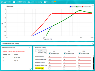
    I'm working on this, but just got one quick question: Are you using TAS2559 in mono application? I think the attenuation you're seeing is due to stereo linking. The EVM has a TAS2560 along with TAS2559, if you're not using the second channel you would need to disable this feature. I'll verify your PPC3 files with this as well and let you know my feedback soon.

    Best regards,
    -Ivan Salazar
    Applications Engineer

  • We've disabled stereo linking and the attenuation doesn't seem to be any better - the excursion graph still reports a rampdown in the output despite never breaching the nominal limits. 

    Of more importance is the performance of this new configuration in our custom hardware. We are able to get audio out in Smart Amp mode, which is an improvement, but the audio quality and volume are both very poor. It sounds like the speaker is submerged in water and the volume is way too low for our application. Furthermore, using the gain registers to try to increase the volume seems to do nothing. The hardware setup we're using is exactly the same as the one we used to characterize the speaker. 

    We again don't know how to proceed. Other than the minor volume issue, this exact characterization works great on the EVM. Error registers INT_DET_1 and INT_DET_2 report no errors at any time in our hardware, so we believe that there is no error condition being encountered. 

    A basic question: how do we simply increase the volume of the output? Register SPK_GAIN_EDGE doesn't affect the volume in any noticeable manner. The gain slider in PPC3 reports writes to several undocumented registers in the I2C monitor when the slider is moved, but writing values to those registers in our code to change the volume also doesn't seem to have any effect. 

  • Hi Sam,

    I've been checking on both files, I noticed Fs is different from ppc.zip file you shared before vs ppc3_working.zip, could you verify which one is correct based on speaker spec?

    I tried to modify some of the settings on both files, I think I'm able to get amplitude more stable on ppc.zip but for some reason, that I have not identified yet, the same changes are not working for ppc3_working.zip.

    • Disable stereo linking, this control is available from Tuning and Audio Processing -> Smart Amp -> Protection Tuning
    • Disable single tone frequency detection. This is a hidden feature that is reducing gain when single frequency tones are detected, this is to prevent early speaker heating
    • Do not sync devices, this control is available from Device Control -> Top right corner

    You can try with this file, however as mentioned, I tried similar changes on your later ppc3 file and did not had the same effect.

    When device is configured in tuning mode, the last stage of the signal path is the speaker protection, thus even if you add digital gain or EQ gain, if speaker protection algorithm is pulling gain down it will still go down regardless of how much gain there is before this stage.

    Best regards,
    -Ivan Salazar
    Applications Engineer

    ppc_102821.ppc3

  • Using this configuration and the above advice, I get a very good and loud output on the EVM. When I try it on our hardware, I get zero noise whatsoever. 

    I need a way to observe the output of the speaker protection algorithm. If something is detecting a danger condition and pulling the output low, I need to be able to see that. The only error registers I see in the documentation are INT_DET_(1/2), and none of those error bits ever go low in our hardware, even when I try to play audio. Are there any other registers I can observe to identify what in the tuning mode pipeline is draining the output? 

    Or, is it at all possible to use 16kHz audio in another mode (ROM modes 1 or 2, maybe?). I know that PPC3 doesn't permit this, but is there a way to get it to work? 

  • Hi Sam,

    I understand your interest on getting signals from specific algorithm results, unfortunately I'm not aware of a way to do something like this. All algorithm aspects are running simultaneously in the DSP and there is no specific way to flag certain events in the process.

    Since TAS2559 is an older version of TAS2563, I would not expect a new PPC3 release to enable 16kHz in ROM mode, but I can try to help by checking what are register differences from 48kHz vs 16kHz in smartAmp mode, and check if the same changes can be used for ROM mode.

    Best regards,
    -Ivan Salazar
    Applications Engineer