This thread has been locked.

If you have a related question, please click the "Ask a related question" button in the top right corner. The newly created question will be automatically linked to this question.

TLV320AIC23: Headphones have current noise

Part Number: TLV320AIC23

Hi team,

I got a question from customer.

The audio solution is made up of 28335PGFA+TLV320AIC23IPW. There will be current noise with ordinary headphones, but the current noise that can adjust the volume of some headphones can be offset. What is the problem?

The following is the schematic diagram:

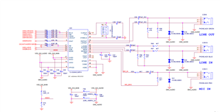
Please make some suggestions,Thank you very much for your help.

Best regards,

  • Hi,

    I'm not exactly clear of the description above, so let's start with the following:

    • Is the codec slave or master? Are you doing a playback (DAC) to headphone output?
    • Can you capture the LRCIN, BCLK?
    • Can you provide your register settings?
    • Do you see issue if you do a loopback as shown below?

    Regards,

    Peter

  • Hi Peter,

    Thank you for your help.

    1. The encoder is the host, and there will be noise whether output or not.

    2. The external crystal oscillator of the decoder is 12M. Then use an oscilloscope to measure the frequency of lrcin pin is 44.1KHz, and the frequency of BCLK is 12Mhz.

    3. Settings:

    AIC23Write(0x00,0x17);

    Delay(100);

    AIC23Write(0x02,0x17);

    Delay(100);

    AIC23Write(0x04,0xf9);// 0x7a

    Delay(100);

    AIC23Write(0x06,0xf9);// 0x7f

    Delay(100);

    AIC23Write(0x08,0x72);// 0x1a

    Delay(100);

    AIC23Write(0x0A,0x00);

    Delay(100);

    AIC23Write(0x0C,0x00);

    Delay(100);

    AIC23Write(0x0E,0x43);

    Delay(100);

    AIC23Write(0x10,0x23);

    Delay(100);

    AIC23Write(0x12,0x01);

    Delay(100);

    4. According to the circuit settings provided by you, there is noise. The following picture has the problem of noise whether it is set to 0 or 1.

    Thanks a lot.

    Best regards,

  • Hi,

    Can you help verify the registers again? It does not look right per the register map in the datasheet.

    See my comments in the attached sheet.

    Register.xlsx

    You should enable the LINE input and use bypass to send the output to LINE output first to confirm the audio quality.

    Regards,

    Peter

  • Hi Peter,

    OK, thank you for your answer,

    I have two questions:

    1. Whether the filtering part of the schematic diagram is correct?

    2. Our register is written according to the data manual of 23B. I don't understand the incorrect part you refer to, or do you have a general reference?

    Best regards,

  • Hi,

    1. That's fine.

    2. Here are few clarification I need from your registers above:

    • When you write AIC23Write(0x00,0x17), is this register address (0x00) follow by data (0x17)?
    • In the datasheet section 3.1.3 the register map starts from address 0x00 to 0x0F, but your registers ends at 0x12. 

    • Your registers only set the even registers and the data values don't seem to match your test path. Can you clarify and explain how do you set the register and its data?
    • In the register map, the register has 9 bits data for example shown below and yours is only 8 bit data.

    Maybe we are looking at different datasheet, can you clarify?

    Regards,

    Peter

  • Dear,

    1. We use I2C to send, I2c is 8bit to send, but the register address is 7bit, so we did a shift (left shift 1bit) before sending the code,
    0000000 -> 1bit left shift -> 0000000
    0000001 -> shift left 1bit -> 0000002
    0000002 -> shift left 1bit -> 0000004
    0000003 -> 1bit left shift -> 0000006
    0000004 -> 1bit left -> 0000008
    0000005 -> shift left 1bit -> 000000a
    0000006 -> 1bit left -> 000000c
    0000007 -> 1bit left -> 000000e
    0000008 -> 1bit left -> 0000010
    0000009 -> 1bit left -> 0000012
    000000f -> shift left 1bit -> 000001e

    2. The register value is 9bit, but I only use 8bit here, and we have no configuration for the highest bit
    Do you have the correct register configuration? Send me a copy. If there is any MCBSP configuration, send me a copy. Let’s refer to the timing configuration. We use 16bit. Let’s refer to it. Thank you

  • Hi,

    Thanks for explaining your register transaction and now it makes more sense.

    I'd recommend changing 2 of the register values shown in the attached sheet and then I need you to provide the scope capture of LRCIN, BCLK, MCLK and DIN if issue persist. This is likely clock and format mismatch.

    6685.Register.xlsx

    Please make sure you are following the DSP format as in the datasheet Figure 3-8 since you are using the DSP mode of 44.1KHz sampling.

    Regards,

    Peter