This thread has been locked.

If you have a related question, please click the "Ask a related question" button in the top right corner. The newly created question will be automatically linked to this question.

PCM5242: SNR test conditions

Part Number: PCM5242

Hi team,

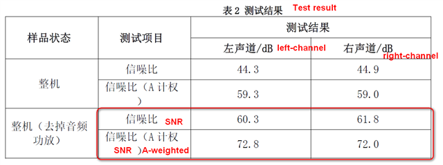
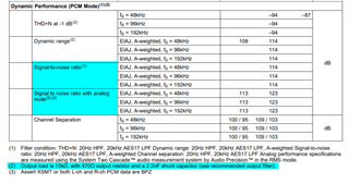
The SNR tested by one of our customers is lower than the value marked in the datasheet. I would like to confirm the SNR test conditions. Is the SNR marked in the datasheet measured at the RC filter output or at the output pins (OUTRP \ OUTRN \ OUTLN \ OUTLP )of pcm5242 ?

schematic:

R96_3568_audiodriver_V1D0_20210824 (1).pdf

Best Regards,

Amy Luo

  • Hi Amy,  it is mentioning the A-weighted filter was used for this measurement, It is  at the output of the filter.

    Regards,

    Arash

  • Hi Arash,

    Sorry, at first I didn't understand the meaning of A-weighted. Now I know that the SNR measured by the customer is also A-weighted, but it is lower than that in the datasheet. What may be the reason for this?

    Best Regards,

    Amy

  • Hi Amy, When you say SNR is lower , what is the value that they are getting?

    Also please remember SNR is a measurement that describes how much noise is in the output of a device in relation to the signal level, so it is dependent on signal level.

    Another question is how they are measuring SNR? are they using AP?

    Regards,

    Arash

  • Hi Arash,

    The customer's test results are shown in the figure below. The left channel SNR (A-weighted) is 72.8 dB. The right channel SNR (A-weighted) is  72dB. 

    The specific steps of the test are as follows:

    (1) Turn on the tested sample and adjust the media playback volume to the maximum;

    (2) The audio output terminal of the tested sample is 3.5mm audio interface, insert a cable (32 Ω resistance), and the other end of the cable is connected to the audio analyzer;

    (3) The measured sample plays a 1kHz, 0dB sound source and measures the amplitude of the output signal;

    (4)  The measured sample plays the mute file and measure the amplitude of the output signal.

    (5) Calculate the signal-to-noise ratio.

    Best Regards,

    Amy

  • Hi Amy, Have  they measure the noise floor by duplicating  Figure 16. 1 or other figures in DS,  may be they would see that their noise floor is much higher than what is expected .  If so, I  would say their board  and setup( routing and cables) needs to be checked and optimized. 

    Another possibility is that there is an attenuation of input signal and they are not really sending 0db as their input. 

    SNR is made up these two components and one or the other is not what they think it is.

    Regards,

    Arash