This thread has been locked.

If you have a related question, please click the "Ask a related question" button in the top right corner. The newly created question will be automatically linked to this question.

OPA1637: schematic review

Part Number: OPA1637

Hi,

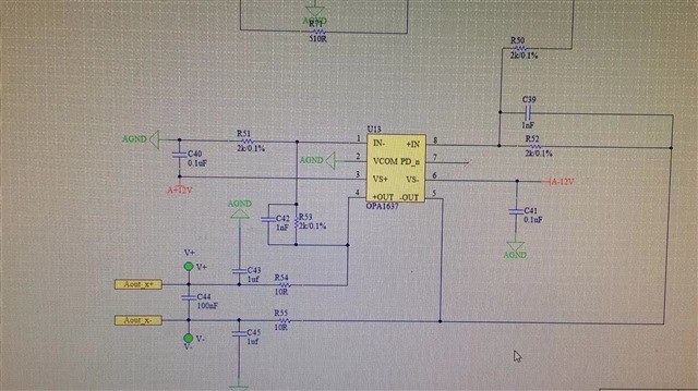
Our customer is using OPA1637. When the input signal is below 1V, the output signal is normal. But when the input signal is more than 1V, the output signal is distorted. Please see the schematic as attachment.

Could you please help review the schematic and find the root cause? Thank you in advance.

Kevin Xiong

  • Hi Kevin,

    The first requirement here would be to assure stability.  The output capacitance you have shown is quite high, and, while you have isolation resistors in place (R54, R55, I'll refer to them as RISO) they are not high enough resistance.  Attempting to drive high output capacitance will lead to instability for most amplifiers, single-ended or FDA.

    The data sheet shows a graph of required isolation resistance for a 40 degree phase margin:

    Your circuit has 100 nF differentially connected and 1 uF to GND; with this output capacitance, a much higher RISO is necessary. If connect that circuit in TINA as shown below I can generate open-loop gain, which will tell us the phase margin of the circuit:

    In this case, the phase margin is just over 10 degrees, which is marginally stable and not recommended.

    Increasing RISO to 60 Ohms raises the phase margin to approximately 40 degrees, which is the minimum recommended:

     OPA1637_filter_stability.TSC

    I've included the file I used for this stability analysis if you want to try some other combinations.

    Let me know if this corrects the issue.  Please be aware we will be on Thanksgiving break until next Monday, Nov. 29th, so responses may be delayed.

    Regards,
    Mike