This thread has been locked.

If you have a related question, please click the "Ask a related question" button in the top right corner. The newly created question will be automatically linked to this question.

TAS5711: Summation of L + R channels on the sub output

Part Number: TAS5711

Hello folks, 

I have a problem with the summation of the L + R channels on the sub output of the TAS5711 chip.
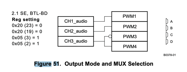
According to the datasheet, the SUB output performs a summation of the left and right channels.
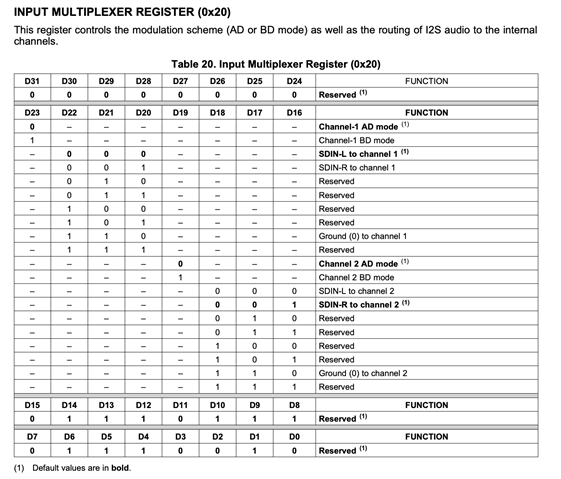
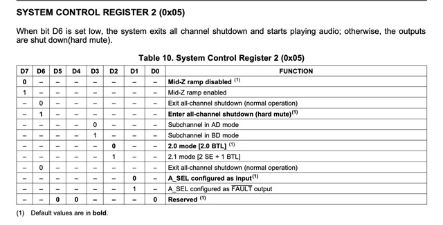
And it doesn't seem to be necessary to create a particular modification. If it is not to be put in 2.1 mode and in BD.
But on my side, on the evaluation card or on my own design, I get only the left channel in my SUB output.

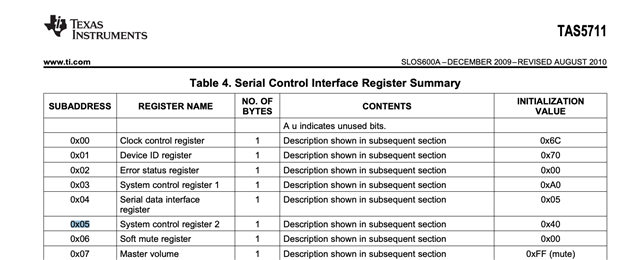
Is it necessary to modify a register?
Or add a component?
To get the L + R on the sub?

Thanks to all for your help.

  • Hello Pierre,

    Please confirm your I2C configuration is correct as outlined in the datasheet https://www.ti.com/lit/ds/symlink/tas5711.pdf in Figure 51 and the section titled 2.1-Mode Support.

    The sub channel sums both channels.

    best regards,

    Luis

  • Thanks for your feedback Luis ! 

    Do you advise the AD mode or BD mode ? 

    The diagram has circles. What does this symbol mean in input or output? Is it a phase opposition? 

    Thanks 

  • I need a clarification. 

    If I want to do this : 

    I need to configure the register like that : 

    X20 00 00 00 00
    X05 00 01 01

    ?
  • Hello Pierre,

    See https://www.ti.com/lit/an/slaa701a/slaa701a.pdf on the information on AD modulation and BD modulation. The circle indicates an inversion/phase shift.

    Refer to the datasheet on the register configurations. your script seems correct but read back the registers to confirm you properly configured the device.


    best regards,

    Luis

  • Thank you Luis for the document. I just read it and found it very helpful and accurate.

    I just looked at the configuration on the GDE (graphical interface).
    I can edit the InMux (which represents the X20 register). I put BD modulation and SDIN1_L for the CH1 part and SDIN1_R for CH2.

    The Mode is Mode_2_1, TAS5711, ModScheme : BD

    But here is what comes out of the I2C configuration file:
    X20 00 89 77 72
    It doesn't seem to correspond with figure 51.
    In fact I don't understand the numbers between brackets on figure 51.
    0x20 : register 20
    (23) : I don't understand the reference. Can you help me?
    0 : value of the register. But 0x20 is a register with 4 variables. What is the variable I have to modify?

    Then X05 is a register with only one variable.


    So I don't understand (3) and (2) in Figure 51.
    In my I2C config file I have : X05 8C
    So 0x05 at a value of 140

    Can you help me understand the situation?
    What should be the values of the I2C configuration file?
    Thanks in advance!

  • Hello,

    The (3) refers to the bit in that register so like 0x05(3) would refer to like D3 if you look at the register map at Page 49 of the datasheet. Look at Page 55 and 49 and see the bit you need to modify for that register.

    best regards,

    Luis

  • The situation is clearer for me but I can't get the Sub to work with an L+R signal.
    I give you a summary of the situation here.

    ! I2C Configuration file for TAS570x
    X1B 00 
    X06 00 
    X1A 0A
    X0A 08 
    X09 1C 
    X08 1C 
    X14 48 
    X13 A0 
    X12 60 
    X11 B8 
    X0E D1 
    X20 00  01  77  72
    X10 02 
    X0B 00 
    X10 02 
    X1C 02 
    X19 30 
    X25 01  01  32  45 
    ! Biquads
    X50 00  00  00  00
    X29 00  80  00  00  00  00  00  00  00  00  00  00  00  00  00  00  00  00  00  00 
    X30 00  80  00  00  00  00  00  00  00  00  00  00  00  00  00  00  00  00  00  00 
    X2A 00  7E  EB  8A  0F  81  14  76  00  00  00  00  00  7D  D7  14  00  00  00  00 
    X2B 00  80  00  00  00  00  00  00  00  00  00  00  00  00  00  00  00  00  00  00 
    X2C 00  80  00  00  00  00  00  00  00  00  00  00  00  00  00  00  00  00  00  00 
    X2D 00  80  00  00  00  00  00  00  00  00  00  00  00  00  00  00  00  00  00  00 
    X2E 00  80  00  00  00  00  00  00  00  00  00  00  00  00  00  00  00  00  00  00 
    X2F 00  80  00  00  00  00  00  00  00  00  00  00  00  00  00  00  00  00  00  00 
    X58 00  80  00  00  00  00  00  00  00  00  00  00  00  00  00  00  00  00  00  00 
    X59 00  80  00  00  00  00  00  00  00  00  00  00  00  00  00  00  00  00  00  00 
    X31 00  6F  66  7A  0F  21  33  0C  00  6F  66  7A  00  DC  A3  A9  0F  9F  09  C2 
    X32 00  80  00  00  00  00  00  00  00  00  00  00  00  00  00  00  00  00  00  00 
    X33 00  80  00  00  00  00  00  00  00  00  00  00  00  00  00  00  00  00  00  00 
    X34 00  80  00  00  00  00  00  00  00  00  00  00  00  00  00  00  00  00  00  00 
    X35 00  80  00  00  00  00  00  00  00  00  00  00  00  00  00  00  00  00  00  00 
    X36 00  80  00  00  00  00  00  00  00  00  00  00  00  00  00  00  00  00  00  00 
    X5C 00  80  00  00  00  00  00  00  00  00  00  00  00  00  00  00  00  00  00  00 
    X5D 00  80  00  00  00  00  00  00  00  00  00  00  00  00  00  00  00  00  00  00 
    X5A 00  00  03  1D  00  00  06  3A  00  00  03  1D  00  FC  72  05  0F  83  81  85 
    X5B 00  00  03  1D  00  00  06  3A  00  00  03  1D  00  FC  72  05  0F  83  81  85 
    
    
    ! DRCs
    X3A 00  7F  FF  B4  00  00  00  4B 
    X3B 00  7F  FF  B4  00  00  00  4B 
    X3C 00  7F  FF  B4  00  00  00  4B 
    X40 FC  83  10  D4 
    X41 0F  83  33  34 
    X42 00  08  42  10 
    X46 00  00  00  00 
    X39 00  00  00  00  00  00  00  00 
    X3D 00  00  00  BC  00  7F  FF  3F 
    X3E 00  00  02  F8  00  7F  FD  05 
    X3F 00  00  00  5D  00  7F  FF  9D 
    X43 FF  AA  F5  6A 
    X44 0F  00  00  00 
    X45 00  08  42  10 
    X46 00  00  00  00 
    X52 00  80  00  00  00  00  00  00  00  00  00  00 
    X60 00  00  00  00  00  80  00  00 
    X53 00  80  00  00  00  00  00  00  00  00  00  00  00  80  00  00 
    X54 00  80  00  00  00  00  00  00  00  00  00  00  00  80  00  00 
    X56 00  80  00  00 
    X57 00  02  00  00 
    X51 00  80  00  00  00  00  00  00  00  00  00  00 
    X55 00  80  00  00  00  00  00  00  00  00  00  00
    X52 00  80  00  00  00  00  00  00  00  00  00  00
    X1A 0A
    X05 8C 
    

    Here is the configuration I would like to upload.
    It is a TAS5711 in 2.1
    Mode : SE - BTL-BD

    So the register X20 need to be: 

    Parametre 4 : 01110010 Hexa = 72
    Parametre 3 : 01110111 Hexa = 77
    Parametre 2 : 00000001 Hexa = 1
    Parametre 1 : 00000000 Hexa : 0

    X20 = 00 01 77 72

    Then the register X05 need to be:

    0X05 : 10001100 Hexa = 8C

    0X05 = 8C

    As you can see my init file is following this rules. But the result is the same. 

    Could you help me more with this point? 

    Thanks for your feedback

    Pierre

  • Hello Pierre,

    When using the TAS57X1 GDE software to configure the EVM are you seeing the same issue? or only when writing your init file.

    best regards,

    Luis

  • Hello Luis, 

    I just tried this configuration and I have the same problem on the development board.
    I checked the registers manually. They are all on the right values.
    What do you recommend?
    Do you think there is an internal routing problem? And that it is not possible to get the Sub L+R?

    Best regards, 

    Pierre

  • Hello Pierre,

    I found the issue. The GUI is not configuring properly the amplifier for 2.1 mode. Please use the attached script where you can find the correct register configuration for 2.1 mode.

    You must use I2C Memory tool to load the script

    2p1Mode-TAS5711.cfg 

    best regards,

    Luis