This thread has been locked.

If you have a related question, please click the "Ask a related question" button in the top right corner. The newly created question will be automatically linked to this question.

TLV320ADC3101: About AGC and PGA Settings

Part Number: TLV320ADC3101
Other Parts Discussed in Thread: TLV320AIC3101

Hi,

I don't know if I understand the register Settings correctly:

My camera wants to record in a noisy environment, and expects the output is stable at 78dB,but the ambient volume is about 90dB, so I want to use the AGC function.

skl_device -R "0x00,0x00;"//write in page 0

skl_device -R "0x0f,0x00;0x10,0x00;"//PGA gain =0dB

skl_device -R "0x13,0xc4;0x16,0xc4;"//input level control gain =-12dB

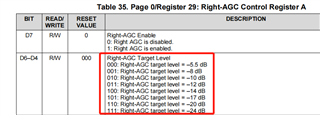
skl_device -R "0x1a,0x8c;0x1d,0x8c;"//AGC target level =-5.5dB,attack time =20ms,decay time=100ms

skl_device -R "0x1b,0x00;0x1e,0x00;"//AGC max gain =0dB

skl_device -R "0x20,0xe8;0x21,0xe8;"//Left-AGC gain =-12dB

skl_device -R "0x1c,0x7d;0x1f,0x7d;"//noise threshold =-88dB

skl_device -R "0x0c,0xa0;"//HPF Fc=600Hz

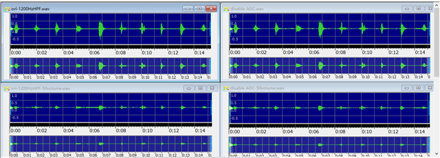
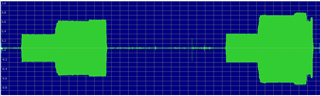
After I set this register, the recorded sound becomes very quiet,In about 35 db.

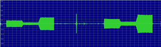
Meanwhile,if I record a 60dB source, my PGA gain and AGC max gain  are set to 42dB, and input level control gain and Left-AGC gain from -12dB to 0dB,

the recorded sound was only about 68dB, only 8dB increse.

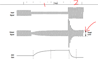
How do I set the target value for AGC?  I don't quite understand the meaning of target level described in the specification.

Please help. many thanks.

  • AGC tries to maintain an average constant level going into the ADC despite large variations in the input signal 

    The Target level is an average level of signal that the ADC tries to maintain going into the ADC. For a single ended input the full scale signal into the

    ADC is 0.7vrms. When we set a target Level 0f -5.5db the AGC adjusts the PGA gain such that the signal level going to the ADC is 5.5db below Full scale Value.

    20*Log(Gain)=-5.5

    10^ (-5.5/20)=0.53  or 0.53*0,7=0.37 Vrms going into the ADC.

    When the input signal goes down such that the input to the ADC is less then 0.37v the PGA  gain increases to bring the signal to the level. If the input

    signal is too large then PGA gain reduces to bring down the ADC input to 0.37v.,

    The diagrams show this. 

  • Hi,

    Sorry for taking so long to reply.

    I made a verification.I turned on the AGC function and recorded in 100 volume and 50volume respectively, and then turned off the AGC function and recorded in 100 volume and 50volume respectively.

    The expected result is that when the AGC function is enabled, the volume of a 50volume recording is higher than that of a 50volume recording without the AGC function.

    But the results are pretty much the same.

    Is this normal? I feel that the AGC function is not enabled successfully.Or my operation is wrong, please correct

    many thanks.

    Tiger

  • I was looking at these graphs you have sent. It looks that you are trying to send bursts of signal. You could try sending a continuous sine wave and increase the amplitude slowly to see if the output amplitude remains constant at target level

  • I used a continuous sine wave to verify, and the result is shown below:

    The waveform on the left in graphs is AGC enabled and the right one is not.

    my register setting:

    skl_device -R "0x00,0x00;" //write in page0
    skl_device -R "0x0f,0x64;0x10,0x64;" //PGA gain=50dB
    skl_device -R "0x1a,0x8c;0x1d,0x8c;" //enable AGC and target level =-5.5,attack time 20ms,decay time 100ms(skl_device -R "0x1a,0x00;0x1d,0x00;" //disable AGC )
    skl_device -R "0x1b,0xc8;0x1e,0xc8;" //AGC gain max=50dB
    skl_device -R "0x1c,0x00;0x1f,0x00;" //Noise/silence detection disable
    skl_device -R "0x6b,0x00;" // enable default coefficients
    skl_device -R "0x0c,0xf0;" //cut-off frequency=1200Hz

    I don't know how to determine the current target level.

    May I ask whether I have done the verification correctly?

    Can you confirm whether AGC has been successfully enabled according to the performance in the picture?

    please help.thanks

    Tiger

  • Hi Tiger,

    Sanjay will continue to help you with this, but I wanted to give some immediate feedback. Remember that target level is the average output level that the AGC will hold your signal at. You should see your output is average at 0.37 Vrms if it is working correctly. However it is still difficult to tell if your output is correct based on the pictures since there are no units on the plot. There is no comparison between input and output. The time units are also necessary to verify the delay and attack times are accurate. My recommendation is to use a continuous input signal with a similar shape to the one Sanjay provided in the picture above. Compare that input with the resulting output. This will provide a better test of target level, delay time, and attack time.  

  • I am a little confused

    Below is your register to enable AGC 

    "0x1a,0x8c;0x1d,0x8c;" //enable AGC and target level =-5.5,attack time 20ms,decay time

    Should not we write    0x56,0x80 to enable AGC and target level =-5.5,

    Also Is  the waveform. th DIgital output ? Are there some dimensions i can see?

    1.we can start by keeping AGC  off.

    2.The with register 59 ,Page 1set a PGA Gain of 20db. (gain of 10)  

    3. Give an analog signal of 70mvrms at input of left channel The ADC should read full scale value . A larger signal will clip ADC output.

    4. Turn on ADC. Target level =-5.5 With Page 0 Register 86. With register 74 set Max AGC gain of 40 db


    An analog input of 0.7V rms to ADC input gives full scale Value.

    -5.5db=20*log(Gain)

    Gain=10^(-5.5/20)=0.53

    Therefore 0.53*0.7=0.37vrms would be the target value seen on ADC input.or roughly half of full scale value


    5. Ater turning on AGC The output should reduce to half the original value as AGC tries to reduce output to about 0.37v. 

    6. Reduce input to 35 mv. The output will remain same at 0.37 v.

  • Thank you so much for your reply.

    I'm sorry that I made a mistake about the part number. It should be TLV320AIC3101.

    should i submit another question, or i can verify it according to the method you mentioned only the registers are set differently?

  •  There's one more thing I'd like to ask that the relationship between PGA setting and AGC  max gain setting, are they have to equal, or they are independent settings ?

  • I took a brief look at the AIC device. The AGC Circuitry in both chips looks to be the same. This means that you can apply the procedure i suggest with the appropriate register settings for the AIC chip.

    When AGC is off , the PGA Gain can be set by I2C in order to get the correct signal to the ADC input. Since ADC input maximum signal for Full scale value is 0.7vrms, the maximum input signal should be scaled by the PGA Gain in order to reach 0.7Vrms.  If Maximum input for example is 70mv then we can set the PGA Gain to 10 in order that we get 0.7v at the ADC.

    I don't see this specifically mentioned in the datasheet but I feel that PGA Setting and Max AGC settings should be  independent. You should keep the Max AGC Gain High so that when AGC is applied, the algorithm can bring even small signals to target level. For example if the Target is 0.53v rms and we set a max Gain of 100 (40db), even a 5.3mv Signal can be scaled by the AGC Algorithm to reach 0.53vrms.

    The PGA gain should revert to PGA setting once AGC is turned off.

     You could start off as a test by keeping the 2 Values same.