A related question is a question created from another question. When the related question is created, it will be automatically linked to the original question.
If you have a related question, please click the "Ask a related question" button in the top right corner. The newly created question will be automatically linked to this question.
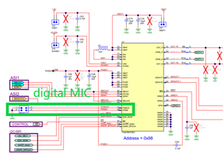
TAS2563 support PDM Microphone inputs. Two PDM microphone inputs simplify audio signal chain for two-way audio systems, interfacing digital microphones with the host processor.
Hardware Connections
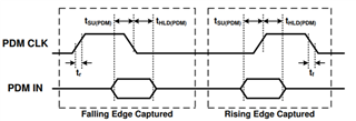
The PDM MIC usually needs two signals to work besides the power supply. It is PDM CLK and PDM Data. The PDM data can be available at the rising edge or falling edge of PDM CLK.
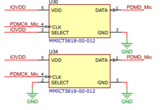
After setting, one of the PDM Mics works at CLK raising edge and the other one PDM Mic works at CLK falling edge, the two PDM Mics can be connected together. The chipset will read the data both at raising edge and failing edge and then split them in two sets of data.
As an example, the PDM Mic has 5 pins, shown in the table below. The ‘select pin’ can be set high or low to determine which signal level makes the Mic data available.
Pin #
Pin Name
Type
Description
1
DATA
Digital O
PDM Output
2
SELECT
Digital I
Lo/Hi (L/R) Select
Connect to VDD or GND
3
GROUND
Power
Ground
4
CLOCK
Digital I
Clock Input
5
VDD
Power
Power Supply
On TAS2x63EVM, the two Mics are connected together, but the select pins are set to low or high in different level. The two Mics work independently in the system.
Device Configuration and Data Processing
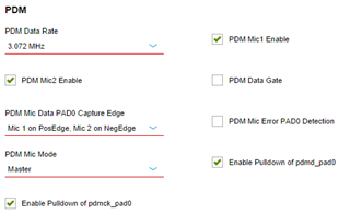
The PDM inputs are sampled by the PDMCLK pin, which can be configured as either a PDM clock slave input or a PDM clock master output. The PDM_MIC_EDGE and PDM_MIC_SLV register bits select the sample clock edge and master/slave mode PDM inputs. In master mode the PDMCLK pin can disable the clocks (and drive logic 0) by setting the PDM_GATE_PAD0 register bits low. When configured as a clock slave, the PDM clock input does not require a specific phase relationship to the system clock (SBCLK in TDM/I2S Mode), but must be from the same source as audio sample rate. This is equivalent to 64/32/16 (~3 MHz) or 128/64/32 (~6 MHz) times a single/double/quadruple speed sample rate. The PDM rate is set by the PDM_RATE_PAD0. When PDMCLK pin is configured as a clock master, the TAS2563 will output a 50% duty cycle clock of frequency that is set by the PDM_RATE_PAD0 and register bit (64/32/16 or 128/64/32 times a single/double/quadruple speed sample rate).
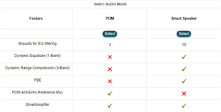
The internal DSP processing features are repurposed to enable the PDM interface, notice from PPC3 software the listed differences for each case.
The PDM hardware interface configuration is configurable within Device Control panel as shown in the following picture.
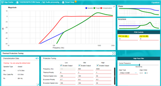
The digital gain control for each of the channels is accessible at Tuning and Audio Processing panel.
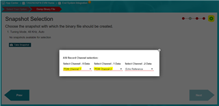
And the ASI configuration to feed back the PDM Mic data is available at the End System Integration panel, at the snapshot selection step as highlighted in the following capture.