Hi there, can the PCMD3140 output two PDM clocks? Using both PDMCLK_GPO1 and GPIO1?
Would these clocks be buffered?
This thread has been locked.
If you have a related question, please click the "Ask a related question" button in the top right corner. The newly created question will be automatically linked to this question.
Hi there, can the PCMD3140 output two PDM clocks? Using both PDMCLK_GPO1 and GPIO1?
Would these clocks be buffered?
Hi Daniel,
Sanjay our ADC support engineer is out of the office and we will get back to you by Wednesday.
Brian
Hi Sanjay, that is not the original question.
Can the PCMD3140 output two PDM clocks? Using both PDMCLK_GPO1 and GPIO1?
We want to avoid using a buffer if possible

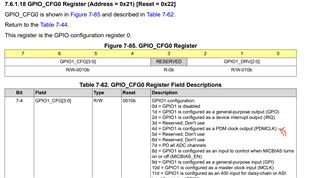
Please see red Marking: It indicates that GPIO1 Can be setup to output PDM CLK

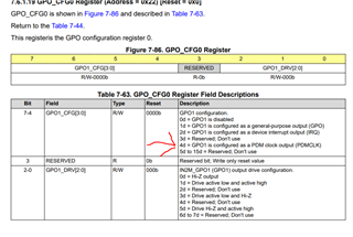
The above table shows that GPO pin can be setup to give PDM Clk
Can both PDMCLK_GPO1 and GPIO1 be run at the same time?
ie. can we treat them as two buffered outputs?
Hi Daniel,
I saw your previous thread and it's hard to say for certain whether you will need a buffer because of things like what kind of cable you're using, length of the run, environmental interference, etc. However, you can certainly run both GPO1 and GPIO1 simultaneously as PDM Clock Outputs. That is possible.
The data sheet shows an example of running two PDM mics off the same output with no mention of a buffer. Any requirement of a buffer will likely come down to the specific application and environment your device is in.
Hi Jeff, thanks for the response.
We understand that you can run 2 mics - we are trying to run 4.
As long as we can run two PDM clocks for 4 microphones simultaneously, we should be fine. Can you please confirm that this is possible and that two outputs are already buffered?
The EVM schematic shows buffers on the pins, so I'm inclined to believe that they are buffered on the IC. I can't promise that they are, since information that low level isn't available. Even if they are, it doesn't eliminate the problems such as line capacitance and the other environmental factors discussed earlier. I'm on the side that you don't need one, but again, I can't promise it.
Thank you,
Jeff
Do you mean that there are no buffers on the pins?
Can you ask your team for the internal IO structure for these pins? I would really like to get to the bottom of this...
We can take this offline if needed.
Let me attempt an approximate analysis .Its not exact but attempts to help the design decisions. please let me know your thoughts.

Please refer to the above figure that gives an indication of the drive capability of the CLK Pins.
Assume a Vcc of 3.3v ,a Rise Time of 18ns is shown from a 10 % (0.3V)to 90%(3V) level. With a 20p load
This means a voltage span of 2.7v.
Assume the driver to be a constant current source driving a load Capacitance.
V=I/C*Ton
I=V*C/Ton
I=2.7V*20p/18n
I=3ma. The drive strength of the pin comes to be 3ma.
lets assume there is no long cable going to the Microphone adding capacitance. This is best case .
Lets assume each Input pin of the Mic is a 15p Load. Lets take a case when one CLKoutput drives 2 Mics.
2Mics is 30p Load.
Tr= 2.7v*30p/3ma
Tr=27ns Tf=27ns

The Datasheet talks of a minimum High and Low time for PDM clock of 72ns. Let us try to obey this specification
T> Thmin+Tlowmin+Tr+Tf.
T> 72n+72n+27n+27n
T>198n
Fclk <5.05Mhz. As long as the Frequency is less then 5.05Mhz , a single output driving 2 15p input Mics would work,
Thank you for the analysis.
We are using a 1.8V supply and not 3.3V.
Additionally, we just want to understand if both PDM clks can be used at the same time and if they are individually buffered.
Hi Daniel. You can use both PDM clks at the same time. Sanjay is researching with our design team to see if those pins are buffered.
Thank you,
Jeff
I discussed with the designed team.
I assume a capacitor load is connected externally from pin to ground.
The below model can be applied:
When the Pin is driven High, an internal current source charges this Capacitor up to Vcc. When the pin is driven low, an Internal current sink discharges this capacitor to ground
With 3.3v Supply the Current source and sink can be considered 3ma
With 1.8v Supply the Current source and sink can be considered 1.5ma.
Both PDM Clks can be modelled as such.
Understood.
If we are using two independent clocks and load one with a large capacitance, will the other be affected. ie. are the drivers individually buffered
I believe these are independent outputs. Capacitive Load on one should not cause an affect on the other.