This thread has been locked.

If you have a related question, please click the "Ask a related question" button in the top right corner. The newly created question will be automatically linked to this question.

TAS5717: TAS5717 unused pin termination

Part Number: TAS5717

Hello Expert,

I have questions TAS5717's unused pin termination.

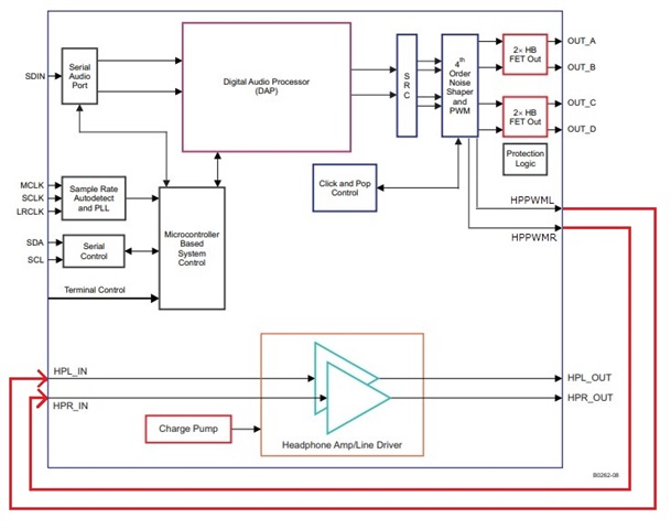
Our customer want to use only head phone out and they don't need to use speaker out.
I guess you will suggest to use different device but they want to use TAS5717 from the point of  view of schematics/board compatibility.

Then, they want to know about which external components can be remove.
Can they treat following pin as open?
OUT_A,B,C,D
BST_A,B,C,D

Also, can they short PVDD_AB/CD to GND or maintain as open when they don't use speaker amplifier portion?

I'm looking forward to hearing back from you.


Best regards,
Kazuki Kuramochi 

  • Hello Kuramochi-san,

    So to clarify they are only using the headphone/line driver and want to completely disable/not use the speaker amp portion of the device? I need to confirm if you can simply ground or left floating the unused pins given the device will not be powered so I will aim to provide an update tomorrow.

    best regards,

    Luis

  • Hello Luis-san,

    Thank you for your swift reply.
    Your understanding is right.
    They want to use only Headphone/Line driver portion.
    Then, they want to know about which pin and external components can be floating or shorting to GND from the point for view of minimizing trace and BOM.

    I'm waiting your update.


    Thank you and best regards,
    Kazuki Kuramochi

  • Hi Kuramochi-san

       Seems headphone driver is controlled by DSP in TAS5717, so there maybe no error can be accepted. If that is the case, only OUT_A,B,C,D can be left open, other pin should connect as normal.

       But Luis will take more time to verify.

  • Hello Kuramochi-san,

    If you ground all the appropriate Speaker amplifier power rails and only power the headphone amplifier and have the components for those HP amp pins you should be able to leave speaker amplifier pins floating.

    best regards,

    Luis

  • Hello Luis-san,

    Thank you for your explanation.

    I understand that they can keep floating for all pins which relate speaker amplifier feature when they supply voltage only for HPVDD and short other power supply pins to GND.
    If there is miss-understanding, please let me know.

    Thank you and best regards,
    Kazuki Kuramochi

  • Hello Luis-san,

    I have additional question for your suggestion.

    This device has UVP which is monitoring PVDD and AVDD.
    Your recommended condition will cause UVP due to both power supply rail will be 0V.
    I guess this UVP only work as muting "Speaker out" and "Headphone out" won't be affected as far as they use headphone out with analog in.
    Is this understanding correct?

    Also, if they want to use headphone out with digital in, can they use this only with DVDD and HPVDD?

    Thank you and best regards,
    Kazuki Kuramochi

  • Hello Kuramochi-san,

    There is no digital input configuration with the headphone amp/line driver it's basically a separate device in the same package. There is only the headphone analog input. The headphone has a separate supply/ground so the UVP wouldn't be relevant as the UVP for the speaker amp not the headphone amp.

    And for your previous question yes the disabled speaker amp can have its supplies grounded and you can optionally ground the input pins, but keeping them floating should be fine since the speaker amp would be disabled when the supplies are grounded.

    best regards,

    Luis

  • Hello Luis-san,

    Sorry for my less information.
    I clarified their actual use case.
    They will use this device as I2S input head phone amp.
    Simplified connection is  as follows.

    At that time they still need to supply power for DVDD and AVDD if HPWML/R is from internal PWM modulator.
    But, I cannot be sure about whether they need to supply power for PVDD and place output inductor, capacitor and bootstrap capacitor.
    Would you tell me about this?


    Thank you and best regards,
    Kazuki Kuramochi

  • Hello Kazuki,

    In this case, they need the full circuit to power the board to avoid potential issues. you wouldn't need the output inductors/capacitors necessarily but the bootstrap caps would be necessary. I think PVDD would be needed to avoid potential faults like the uvp as you mentioned.

    best regards,

    Luis