


Hello TI team,
I'm going to design simple subwoofer amplifier, based on TAS5630B in PBTL mode.
The main idea of the design to keep main TAS5630 board in vertical position, where the rest of components, like main power supply, filters
are located on main board. Boards will be connected using pins. The slave board will be screwed to the radiator directly.
As inductors I'm going to use murata coils 1274AS-H-6R8N
6,8uH, Isat = 7500mA, DC resistance = 0.0213Ω
Output power max 150W (limited by input signal and current limit)
PVDD = +45V
Can you advice regarding slave board? I would like to keep inductors and mid capacitors on the slave 2x1000uF
On the master board, put the 4x2200uF close to slave board:
Size 62mmx30mm
Bottom pcb:
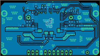
And top:
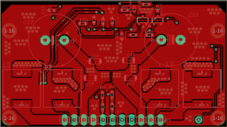
Most of the elements are mounted on top to avoid any shortcut with GND (radiatoror).
best regards
Maciek
