This thread has been locked.

If you have a related question, please click the "Ask a related question" button in the top right corner. The newly created question will be automatically linked to this question.

TAS5760XXEVM: we bought EVK https://www.ti.com/tool/TAS5760XXEVM#description ,now we are in stage of validation

Part Number: TAS5760XXEVM

Dear Team,

we are in the stage of evalution of audio amilifier ,there is option to give external mclk to the IC ,in that i  have some doubts 
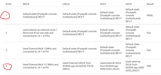
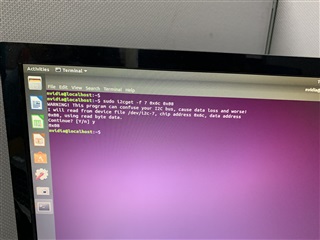
1) iam playing different kind of audio but i got only 48MHz how to changes sample frequency 
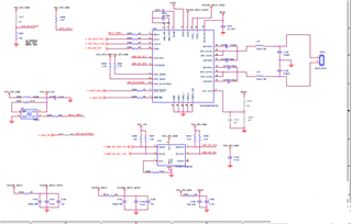
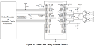
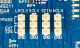
2) if in case i want give external mclk what are the changes required in schematic.

Kindly help us on this stage 

Thanks
pooja ak

  • Sorry ,
    I have to correct the sample frequency in the above mentioned points

    1) iam playing different kind of audio but i got only 48Kilo Hz, how to changes sample frequency 

    Thanks,

    Pooja Ak

  • Hi Ak

    thanks for your question.

    1. i am afraid that the sampling frequency can not be changed on EVM board for it was fixed when the board is made.

    2. there are corresponding pin was reserved on the board, i think you can connect them directly.

    Jesse

  • Dear Jesse
    Thank you for the solve one of my doubt.

    1)Now i have 12MHz( that should be ~256 x fs = 256 x 48kHz=12.28MHz) or does it have to be exactly 12.28?
    Is there any tolerence is there in mclk or else we have to go for exact value ?

    can you please tell me ...

    Thanks 
    Pooja Ak

  • Hi Ak

    No, there is no need for exact clk value. ±10% is allowed.

    but the relevant relationship between each clock is more important.

    thanks.

    Jesse

  • Dear Jesse
    Good Day!

    Then i gave mclk  12MHz as from external oscillator ,rest of the things like LRCLK=48khZ,SCLK=3.072MHz  and DATA are  used from internal (EVK)
    by using this configuration we getting error in error status register [clock error status Bit 3 is set]

    Can you please suggest to us how to generate external MCLK by maintaining relevant relationship between each clock?

    Thanks,

    Pooja Ak

  • hi Ak

    you want to use LRCLK = 48kHz, and transfer 64bit(sclk/lrclk = 3072/48) data? am my understanding right?

    if your mclk = 12Mhz is fixed, i think you need to set sclk = mclk/4 = 3MHz.

    you can take a try with this setting.

    thanks.

    Jesse

  • Helo Jesse

    Yes ,Your understnding is right !and same thing we followed in our PurePathTm Console with the TAS5760xxEVM Board Rev(F)
    But we are facing clock error .

    I have to clearify one thing 
    Here we are giving MCLK in external  oscillator , remaning clock taking from EVK, everthing like LRCLK,sclk, should i take external or what ?

    Requesting you to help us on this .....

     Thanks,

    Pooja Ak

  • Hi Ak

    The mclk input is separated with lrclk, sclk.

    if fs has a little shift, mclk will not shift together, then maybe the relations between each clk will collapse.

    you can keep mclk fix, but the other clock should have below relationship( in your situation.)

    mclk = 256fs. sclk = 64fs. (256 and 64 has to be stable if your mclk can not change. maybe you need to adjust a little fs from EVK)

    But for your situation, even you don't change fs, the clock should be able to work.

    maybe some other root cause lead to your problem.

    can you help confirm the waveform and the frequency for each clock ?

    also check does the sequence normal or not?

    for root cause analysis, can you take a try a smaller mclk clock with specific value, like 128xfs or 192xfs.

    ps. when you trying new clock, please remember clear the error and resume normal operation by toggling the SPK_SD pin.

    about the detail, you can check 8.3.3 in datasheet.

    thanks.

    Jesse

  • Hi Jesse
    Happy weekend !

    Yes will apply mentioned configuration  and will come back soon..

    Thanks,

    Pooja Ak

  • Hello Jesse,

    Posting on behalf of the customer:

    There is no improvment in our below mentioned case .if i give internal clock it's working fine instead of internal clock i provided external mclk and LRCLK , data and also SCLK from NVIDIA .but still we are facing clock error issues

    Thank you in advance and we look forward to your response.

    Regards,

    CSC

  • Attached herein are the scope shots.

    sn_customerservice_case_81c4ed6547130994d4f52e61e36d4351_attachments.zip

    Thank you in advance.

    Regards,

    CSC

  • Hi Ak
    1.before you connect all clk signal from external MCU, have you clear the clock error generated by previous clk error problem?
    2.i checked the clk graph you sent me, it seems you sclk shifts from 3.07->2.82MHz during test which is not stable, but the mclk is very stable.
    Is this a test problem or your sclk is not stable.
    3.Except the clk error, can you help confirm is there any other error can be found from other register?

  • Hi Wei 
    1) when i connect external mclk by that time only iam facing clock error issues.
    2) As soon as possible i will share proper working condition graph and non working condition graph
    3)yeah some time will face Over current error ,other than we didn't face any issues.

    Please find the shared below table which i tried different combination and there result .

    Si No MCLK  LRCLK SCLK DATA Result
    1 Default state (Purepath console motherboard) REV F Default state (Purepath console motherboard) REV F Default state (Purepath console motherboard) REV F Default state (Purepath console motherboard) REV F PASS
    2 used internal as external clock ( Removed R153 one side and connected to J4 1 st Pin) Default state (Purepath console motherboard) REV F Default state (Purepath console motherboard) REV F Default state (Purepath console motherboard) REV F Fail
    3 Used External Mclk 12MHz and connected to J4 1 st Pin  Default state (Purepath console motherboard) REV F Default state (Purepath console motherboard) REV F Default state (Purepath console motherboard) REV F Fail
    4 Used External Mclk 12.3MHz and connected to J4 1 st Pin  Used External LRCLK from NVIDIA agx Som(I2S3_FS) IS 48kHz Used external SCLK from NVIDIA agx SOM (I2S3_SCLK) Used external SCLK from NVIDIA agx SOM (I2S3_DOUT) FAIL 


    Thanks,

    Pooja Ak

  • Hi Ak

    Your 4th setting should work.

    For you have a pass case with default setting, looking forward to your comparison graph betwen 1 and 4.

    if 1's clk is different with 4, can you help adjusting 4 using the same clk with 1 to confirm does 4 can work?

    thanks.

    Jesse

  • Dear 


    Current status of above mentioned issues.
     we replaced PPCB with XAVIER AGX board and connected to TAS5760xxEVM, rev D
    Please find below changes done in the board,if it require any changes to do in hardware please suggest us to do.
    1) conected all LRCLK,SCLK and DIN from  XAVIER AGX.
    2) Connected MCLK 12.28MHz.
    3)GAIN0 and GAIN1 are made high(3.3V)
    4) SPK SD pin gave 2 optional low and high 

    Kindly requesting you to help us on this ,we are traying to do from past 20 days still we are facing same issues.

    Thanks,

    Pooja Ak

  • Hi Ak

    Let me clear something about this issue.

    1.I saw you faced some over current error sometimes, have you found the root cause? how frequently does it happen?

    2.Below 4 situation, can you adjust the clock in 4 the same with the clock in 1, then compare them to see is there any difference?

    3. Last time you send me the clock wav, i found that your sclk clock is not stable which change from 3.07->2.82MHz during test, is this the measurement error or your clock is just not stable.

    4. Can you give me a simple diagram about how you connect your each clock for better understanding.

  • 0x8 is error ryt ! setup pickDear Jessi ji,

    non working clk images.zip1) on initial stage we faced over current error then automatically it went off.
    2)our goal is to verify with nvidia so we replaced from ppcmb to nvidia by that time we can't check over current issues .
     
    As of now we replaced PPCB with XAVIER AGX board and connected to TAS5760xxEVM, rev D


    Please find the attached block diagram for your refrence ,is that possible to talk through so that it wil easy to slove the issues
    Kindly support on this

    Thanks,
    Pooja ak

  • Ak

    Can you send me the waveform for each clock signal?

    when the mclk is separated from other clk, it is easier to happen clk error.

    because the clock jitter maybe different from each clock source, so that their sync relationship been broken.

    this is my email. jesse-ji@ti.com.

    we can talk by email.

    thanks.

    Jesse

  • Dear Jesse iam planning to give below mentioned AUDIO_CLK as MCLK to chip

    Thanks for the much usefull information. in XAVIER AGX there will be one AUDIO MCLK .now iam going to giving audio mclk to chip 
    will see how it will react .


    Thanks,

    Pooja Ak

  • Dear  Jesse

    I just gone through Audio forum ,one of your customer has faced same issues like us ( https://e2e.ti.com/support/audio-group/audio/f/audio-forum/1091769/tas5760m-inquiry/4043588?tisearch=e2e-sitesearch&keymatch=%25252525252520user%2525252525253A357730#4043588 )
     here i attached refrence link for your refrence ,please tell me how they generated MCLK in there end ,so it will be use full to me also .to slove the  clock  error issues
    In our end ,64 bit and mono mode apart from that everything have same. 64 bits and mono mode

    Requesting you to help on this .

    Thanks,
    Pooja Ak

  • Hi Ak

    About the ticket you measured, we don't know the information about how they provide the clock.

    there is a recommend circuit in the datasheet as below, mclk can be provided by the mcu.

    thanks.

    Jesse

  • Dear Jessi

    Thanku so much !we will try above mentioned configuration and will come back.

    Thanks,

    Pooja Ak

  • Dear jood Day

    We have updated new on the above mentioned issues
    We gave all the signals signals from Som ,and found okay(working)
    Thanku for the continues support,

    Thanks,

    Pooja Ak

  • Dear j

    We have updated news of the above mentioned issues.
    Given all the I2S signal from Nvidia SOM and found okay(audio is working fine)
    Thanks for the support !

    Thanks,

    Pooja Ak