This thread has been locked.

If you have a related question, please click the "Ask a related question" button in the top right corner. The newly created question will be automatically linked to this question.

TAS2521: Using TAS2521 with LM4670

Part Number: TAS2521
Other Parts Discussed in Thread: LM4670, TPA2011D1

Hello, 

I am trying to design a circuit using the TAS2521IRGET speaker amplifier with the LM4670SD/NOPB power amplifier.

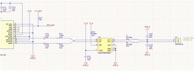
In a previous design, we successfully used a circuit based only on the TAS2521, as can be seen in the next figure: 

TA2521 Audio Amplifier Circuit

However, it turned out that the output power was too small for our needs and we decided to add the LM4670 as an additional amplifier to the circuit.

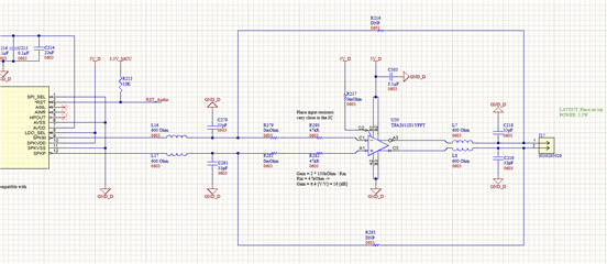
So the new circuit consist of the TAS2521, that is controlled by the MCU through I2S protocol, which is driving LM4670's input. The speaker is then connected to LM4670's output, as described in the next figure:

 TAS251 with LM4670 Circuit

C303, C304, R217 and R342 were chosen according to Figure 32 in LM4670 datasheet. L7, L8, C218, C219 were left from previews design. 

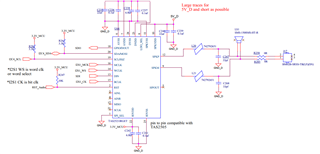
Now, I was reading this threat - LM4670: LM4670SD/NOPB Can't output Sound and it looks like that after implementing the recommended solutions, the original poster's circuit was very much similar to ours. However, he claims that he is getting very low volume levels. 

User's circuit can be seen in next figure, in red are the solutions that were recommended by other users, which I believe that the original poster implemented. 

Immediately, I would suspect that the TA2521 is designed to drive a small impedance speaker, whereas now he has to drive a 0.1uF capacitor and a 150kOhm resistor. But these values come from LM4670 datasheet.

Another idea is the fact that 150kOhm resistors are giving the amplifier only a 6dB gain (as per Equation 2 in LM4670 datasheet) , lowering the resistor's value would increase the gain but decrease speaker's performance (THD+N). 

In any case, I am worried that my circuit would not work given these resistor and capacitor values. How would you recommend connecting these two components together? 

  • Hi Devid,

    My first concern about interfacing TAS2521 to LM4670 is that you're planning to use Class-D output from TAS2521. You would first need to add a LC low-pass filter at the output of the Class-D as the PWM-like signal would most likely not work as input for LM4670.

    Alternatively you may consider using HPOUT instead of SPKP/SPKM, I think a different gain for LM4670 would be needed in that case.

    You may also consider some alternatives for LM4670, this is a legacy part with limited support as there is no EVM or model available. Perhaps TPA2011D1 or similar could work in this application.

    Best regards,
    -Ivan Salazar
    Applications Engineer

  • Hi, 

    Thank you for your reply. I made some modifications based on your advice - I switched the LM4670 to TPA2011D1 and added LC filters.

    Do you believe this design would work? 

  • Hi Devid,

    The updated schematic looks OK. It is usually recommended to use lower gain levels to keep noise low and keep the device on its best operating region, however you may test this and evaluate the performance.
    Your have some room to reduce the cutoff frequency of your RC filters. Those L components are actually resistors, correct?

    Best regards,
    -Ivan Salazar
    Applications Engineer

  • Hi Ivan, 

    The L components are actually ferrite beads, but they could as well be resistors. I think I will replace them with a 30KHz RC filter (1kΩ, 4700pF).

    Thank you for your help,

    Devid