This thread has been locked.

If you have a related question, please click the "Ask a related question" button in the top right corner. The newly created question will be automatically linked to this question.

TAS5760M: Questions about I2C

Part Number: TAS5760M
Other Parts Discussed in Thread: TAS5760XXEVM, , TAS5825M, TAS5828M

Dear teams,

I have 5 questions, so please answer them.

1.

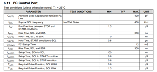
According to 9.2.1.2.1 of the data sheet.
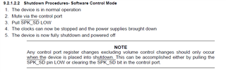
NOTE
"Control port register changes should only occur when the device is placed into shutdown. This can be accomplished either by pulling the SPK_SD pin LOW or clearing the SPK_SDbit in the control port."

However, looking at the operation of the TAS5760xxEVM, it seems that the register value can be changed without shutdown.

Is it possible to change the register value even if it is not in the shutdown state?

Also, in this case, may problems such as restrictions on I2C communication and abnormal operation occur?

2.

When setting using Direct I2C Read / Write on PPC, the length is automatically set to "4" when accessing 0x10 and 0x11 addresses, and an error occurs unless 4 bytes are set.

With Registers, I was able to send with only 1 byte.

What is the difference?

3.

Looking at the I2C waveform of EVM, there is a waiting time of several tens of microseconds from sending the slave address and subaddress to sending and receiving data.

Do it need this waiting time?

If it need to wait, how many seconds do it need?

4.

When I changed the clipper settings using the Block Diagram, the following transmissions and receptions were made.

"0x0 read-> 0x1 read-> 0x1 write-> 0x10 write-> 0x11 read-> 0x11 write"

Do it need a 0x0 read and a 0x1 read?

Also, for 0x11 read, why do it need to read here?

5.

In rare cases, if DigClipLev [19: 0] is dynamically changed while the speaker output is in the "not shutdown" state (SPK_SD PIN is High and SPK_SD of Power Control register is 1), the speaker output will stop and recover.

At that time, SPK_FAULT PIN remains High.

What is the cause of this problem?

Is it possible to avoid it?

Best regards,

S. Miura

  • Hi, Miura.

    I will collect the answers and reply you later.

    BR.

    Wei Qiu.

  • Hi Miura.

    The answers to your questions are as follows:

    1.For the device TAS5760M, in order to avoid unknown instruction conflicts, the read and write operations can only be performed when the power is turned off, and the requirements in the datasheet shall prevail.

    2. About the second question, I don't know your question too much because the TAS5760M is an old device. Usually, writing multiple bytes to a register means writing values to several consecutive registers in sequence.

    3. According to our datasheet, the wait is not mentioned and strictly required. We recommend that you only need to use it according to the I2C rules in the datasheet.

    4. All read operations are unnecessary.

    5.Like the first question, because the registers inside the chip are already in working state, in this case, changing the value of the register in real time can easily lead to unpredictable results. We still recommend that you power off first according to the instructions in the datasheet. Then go to change the value of the register.

    BR

    Wei Qiu.

  • Hi Qiu.

    Thank you for your answer.
    I want to change the digital clip level in real time.

    Please answer any additional questions.


    (1) Looking at the data sheet, it seems that the volume register can be changed in real time.


    The volume register can be changed in real time.
    Unexpected problems occur when the digital clip registers are changed in real time.
    Please tell me what is this difference.

    (2) Would you please introduce a device that can change the level of digital clips in real time?

    Best Regards,

    S.Miura

  • Hi Miura.

    1. At the beginning of the design TAS5760M, only the volume control register can be dynamically adjusted, and other registers need to be shutdown before they can be reconfigured.

    2. Maybe you can open the datasheet of TAS5825M TAS5825M 4.5 V to 26.4 V, 38-W Stereo, Inductor-Less, Digital Input, Closed-Loop Class-D Audio Amplifier with 192-kHz Extended Audio Processing datasheet (Rev. G) (ti.com) and TAS5828M TAS5828M 50-W Stereo, Digital Input, High Efficiency Closed-Loop Class-D Amplifier with Hybrid-Pro Algorithm datasheet (Rev. A) (ti.com) and take a check if these device can satisfy your need. TAS5825M and TAS5828M can both change  the level of digital clips in real time. 

    BR.

    Wei Qiu.

  • Hi Qiu.

    Thank you for your introduction.

    Let me check again.


    ・TAS5760 does not recommend changing digital clips in real time.
    ・TAS5825 / TAS5850 can change digital clips in real time.

    Please tell me the difference between this TAS5760 and TAS5825 / TAS5850 in detail.

    (1)What are you concerned about when changing digital clips in real time on the TAS5760?
    (2)Why is it okay to change the digital clip in real time on the TAS5825 and TAS5850?
    Please tell me specifically.

    For example, if there is a concern that POP noise will occur if the value of the digital clip is changed suddenly, we will responsibly change it step by step.

    P.S.
    Earlier, I told you that the speaker output would rarely stop when I changed the level of the digital clip in real time on the TAS5760, but it turned out to be another hardware factor.
    After taking measures against the hardware factor, it continues to operate normally even if the digital clip is changed in real time.

    Best Regards.

    S.Miura.

  • Hi Miura.

    If we want to be able to modify the registers of the chip in real time, we need to add an additional set of logic circuits to achieve this.
    However, this function was not added at the beginning of the design of TAS5760. If the value of the register is forcibly changed during operation, it is likely to cause the chip to work abnormally.

    If you really need this function, we suggest you to use TAS58xx.

    BR.

    Wei Qiu.

  • Hi Qiu.

    Thank you for your reply.
    I'm sorry to ask you many questions, but please tell me a little more detail.

    1. What role does a logic circuit play?
    2. Is it possible to replace the logic circuit by devising software control?
    3. What exactly is the abnormal operation of the chip?
    ・ Will the value of the digital clip be an unexpected value?
    ・ Or is it possible that other operations may become abnormal?
    ・ Have you actually experienced any abnormal operation?
    ・ Please tell us what kind of content it was if it occurred.

    BR.

    S.Miura.

  • Hi Miura.

     About your question.

    1. You can think that for the TAS57xx, due to the lack of logic circuit, changing the value of a register at runtime is equivalent to a hard direct change, prone to unpredictable errors in the process. In the latest TAS58xx, a logic circuit is added, which is equivalent to adding a buffer after writing, and writing at the right time to avoid errors.

    2. This is not possible because it is related to the design of the chip.

    3. As far as I know, popping noises and some other unpredictable issues are possible. We strongly recommend setting according to the requirements in the datasheet, TI will not be held responsible for any problems arising from non-compliance with the datasheet.

    Thanks.

    Wei Qiu.

  • Hi-Qiu

    Thank you for your reply.

    We have realized that it is difficult to change the value of a digital clip in real time with the TAS5760.

    Thank you for your kind support.


    Best Regards,

    S.Miura.