This thread has been locked.

If you have a related question, please click the "Ask a related question" button in the top right corner. The newly created question will be automatically linked to this question.

TAS1020B DFU mode programming help required - repairing a Line 6 POD HD400 guitar effect units


Hi,

I've recently acquired a faulty Line 6 POD HD400 guitar effects unit which appears to have suffered from a bad firmware flash or EEPROM corruption. I've done some research and this appears to be a somewhat common problem, some people are lucky enough to be able to recover the device by reflashing or downgrading the firmware using the Line 6 Monkey flashing software but in my case the device simply isn't recognised by the Monkey software. The unit displays the error "DSP boot failed" after turning it on and then just displays a blank screen with no response to any inputs. I am able to hold a button to boot in to a test mode and I can see that all knobs and buttons and lights are working correctly, but still can't be reflashed by the Monkey software.

I've done some troubleshooting on various Windows computers and found that my HD400 is detected as an "unknown" USB device with a descriptor of VID_FFFF&PID_FFFE . I'm able to force Windows to install the official HD400 drivers and the device is then listed correctly under the sound devices category, but the Monkey software is unable to detect that the device is connected. I've had another look and discovered that the HD400 uses a Texas Instruments TAS1020B USB controller/streaming audio chip for communication, and the datasheet explains that when the TAS1020B doesn't detect a valid EEPROM image or application then it reverts back to booting in DFU mode with a dummy ID of VID_FFFF&PID_FFFE which matches what I'm seeing.

I haven't been able to locate a copy of the Texas Instruments firmware development kit but I was able to find a copy of the DFU test utility, after installing the DFU drivers I'm able to get the DFUTEST.EXE program to communicate with the HD400.

I gather that it may be possible for me to use the DFU tool to use the TAS1020B to either reflash the EEPROM with a valid firmware image or, at the very least, possibly get the TAS1020B to reboot and report the correct Line 6 POD HD400 ID of VID_0E41&PID_5058 . I'm hoping that if the HD400 can report the correct USB ID to Windows then I may be able to get the Monkey software to correctly detect that the device is connected and then reflash it with the correct firmware.

Can anyone please help me generate the correct file to send to the TAS1020B in DFU mode in order for it to be able to reboot with USB ID VID_0E41&PID_5058 ? I would be very grateful for any help.

Many thanks,

Ameer

  • You need the firmware from Line 6.

  • Hi, thanks for the quick reply. I do have a copy of the firmware from Line 6 (filename is "Pod_HD400_2.01.phf" and is 1182KB in size) but is it OK to flash this directly from the DFUTEST software? Would it have the right header configuration that the TAS1020B will be expecting? I had a quick look at the file and wasn't convinced that the start of the file matched the description of the header format in the TAS1020B datasheet.

    Also, possibly a silly question - but do I use the "download" or "upload" function of the DFUTEST software to transfer the firmware to the TAS1020B? I'd have thought it would be the "upload" function but the gui seems a bit ambiguous here.

    Thanks, Ameer.

  • Hi,

      First of all, I agree with Andy that you will need to get firmware and support from Line 6. As for TAS1020B, I am sorry, we no longer offer direct support for this device on the E2E forum. You may search the E2E forum for archived posts of previous discussions which may help address your questions. Sorry for lack for guidance. 

  • Hi, thanks for the reply. I've already contacted Line 6 and their other associated support partners and none of them have been able to assist ("Sorry, we don't offer tools or software support other than what's on the website, we don't have any spare parts for these devices as they're so old, we don't do out of warranty repairs" etc). It's very understandable but unfortunately has proved to be a dead end.

    I've spent a lot of time recently searching and reading the archived posts elsewhere on this forum which is what has led me here - I've seen that there has been some very useful assistance provided in the past so thought I'd log a ticket with TI support to see what could be done. They weren't able to provide me with the firmware development kit for this device as it's classed as obsolete and they've removed the associated software downloads for this but they have asked me to post on this forum and suggested that I'd be likely to obtain assistance here.

    If you disregard the fact that the TAS1020B happens to have been implemented in a Line 6 product, it becomes a general query - does anybody have a copy of the header utility which they can use to assist me in building an image for a TAS1020B to allow it to present itself as a USB device with the ID VID_0E41&PID_5058 please?

    Thanks,

    Ameer

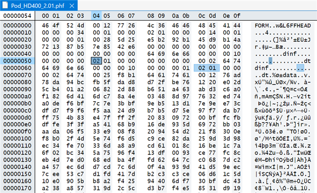
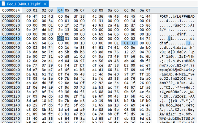
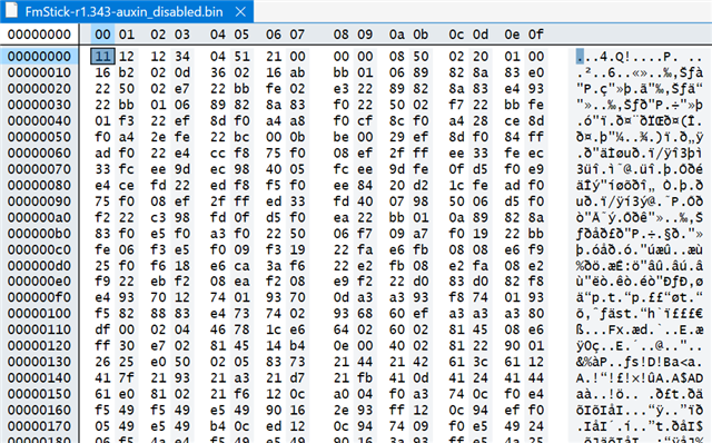
  • A little more info - here's a view of the beginning of two official Line 6 firmware images (v2.01 and v1.31) and one unrelated TAS1020B project firmware. The two official Line 6 firmware images seem to have a lot of extra data and also seem to be missing a few parts that I'd expect to see (e.g. the VID 0e41 and PID 5058 codes). The other TAS1020B project firmware image seems to conform much more to the header structure that I'd expect to see but when I compare it to the documentation in the datasheet I still can't identify all of the parts of the header that I'm looking for.

    This leads me to believe that there's no hope of being able to flash the official firmware directly to the TAS1020B in DFU mode because it looks like the firmware image has been manipulated in order to work with the Line 6 Monkey software.

    Is it at all feasible to try to build a valid header out of the information that's here in order to at least attempt to flash the TAS1020B to get it to be recognised by the Line 6 Monkey software?

    POD HD400 firmware v2.01:

    POD HD400 firmware v1.31

    Random TAS1020B project code:

    Many thanks,

    Ameer

  • Hi,

      I really wish I can help you. You seem to suggest that the ROM bootloader is checking the application header before downloading the firmware. Can you load the unrelated random TAS1020B project code:? We just don't have anyone with the knowledge to answer your question as this device is obsolete.  Sorry for lack of guidance. 

  • Thanks Charles, appreciate your time looking at this for me. I'm only going on what I've read in the TAS1020B datasheet here:

    https://www.mouser.com/datasheet/2/405/tas1020b-557821.pdf

    but according to pages 20-21 it does seem that there's a strict header structure that the TAS1020B will be expecting. My concern is that apparently the TAS1020B only boots in to DFU mode if it finds a corrupt EEPROM image or no EEPROM image at all - I'm afraid that if I flash the TAS1020B with the unrelated project firmware code that I found (I think it's for a radio device) and it is successful then it'll no longer boot in to DFU mode and I'll have no way to communicate with the TAS1020B any more using the DFU tools. From what I've read, the only way to force the TAS1020B into DFU mode again would then be by wiping the EEPROM or shorting something out to prevent it from being seen.

    https://e2e.ti.com/support/audio-group/audio/f/audio-forum/1055331/tlv320aic3262evm-u---stick-evm---how-to-revive-eeprom/3906293

    I also found another thread which seems to indicate that the VID and PID presented will depend on what's contained in the application and not necessarily what's in the header which adds to the confusion:

    https://e2e.ti.com/support/audio-group/audio/f/audio-forum/73900/something-wrong-with-tas1020b-header-utility

    There's also a bit of information here but I think this relates to the TAS1020B development board which has jumpers to control whether or not it boots from EEPROM or RAM:

    https://e2e.ti.com/support/audio-group/audio/f/audio-forum/85533/tas1020b-programming-sequence

    BTW I did find a copy of the original firmware development kit for this device but unfortunately it's not free to download and I'm reluctant to pay for this unless I think there's a reasonable chance that it'll be useful.

    https://www.codebus.net/d-1AhO.html

    I'm starting to think that unless I was able to get an actual firmware file directly from Line 6 which is correctly formatted for flashing to the POD HD400 in DFU mode then it'll be impossible for me to get it in to a state where the Line 6 Monkey software will ever be able to communicate with it. I did ask Line 6 to pass my query onto their software development team but their support rep said they don't have any access to this and that the only available software is via whatever is publicly available for download from their website.

    Many thanks,

    Ameer

  • but according to pages 20-21 it does seem that there's a strict header structure that the TAS1020B will be expecting. My concern is that apparently the TAS1020B only boots in to DFU mode if it finds a corrupt EEPROM image or no EEPROM image at all - I'm afraid that if I flash the TAS1020B with the unrelated project firmware code that I found (I think it's for a radio device) and it is successful then it'll no longer boot in to DFU mode and I'll have no way to communicate with the TAS1020B any more using the DFU tools.

    Not sure what to suggest here really. Why don't you remove the EEPROM so that DFU will download code to RAM instead of EEprom.  I don't know if this is a valid method. Sorry. 

  • My concern is that apparently the TAS1020B only boots in to DFU mode if it finds a corrupt EEPROM image or no EEPROM image at all

    Yep, that was what I remember from doing a TAS1020B design a long time ago.

    My workaround for this? Easy: to force DFU mode, simply short the I2C SDA and SCL lines together while connecting the device to the USB. The micro will not see I2C acknowledges from the EEPROM so it reverts to DFU mode.

    One in DFU mode, remove the short, then run the host-based firmware upload program.

    I used a pair of tweezers to short the I2C lines together. 

  • Thanks for the input Charles and Andy. That's a good idea to try to find the SDA and SCL lines to force DFU mode, I would need to dismantle the unit again and have a look at the board to see if I can identify the relevant points.

    In the meantime I've tried sending the official Line 6 firmware (.hdf file) directly to the device using the DFUTEST application and although it did appear to run all the way through the flashing process (it took about 30mins to complete) after restarting the unit I couldn't seee any difference. The device still shows that it's booting the POD firmware v2.01 and then gives the usual DSP BOOT FAILED error and then a blank screen, which is exactly what it was doing before. The test mode and factory reset modes are also still operational as normal.

    I wasn't really expecting this to work anyway since I could see that the .hdf file header info seemed to be malformed compared to the documentation and the other unrelated project firmware file that I looked at.

    I'm starting to think there's no chance of success at this point - I had been thinking of editing the unrelated project firmware file that I have in order to try to get it to use the Line 6 PID and VID identifier but I realise now that the header checksum would then be invalid and I doubt I'll be able to calculate it manually, so the DFU firmware flash will therefore probably fail regardless.

    Even if I were to try to obtain another working POD HD400 unit and try to dump the EEPROM firmware from that one there's no guarantee that it would contain the actual DFU header information and still might not be useful for resurrecting the unit with bad firmware.

    One last question - does anyone here still happen to have a copy of the TAS1020B original firmware development kit that I could get a copy of?

    Thanks,

    Ameer

  • check your private messages. I have the dev kit.

    Also the I2C EEPROM is probably an easy-to-find SOIC-8, so the tweezer thing will work well.

  • Thank you very much Andy!

    I've just managed to snag another working POD HD400 that's in rough physical shape, when this arrives I'll swap out the working board in to my unit. So I then plan to work on the faulty board some more as I'll have nothing to lose at that point. I'm also toying with the idea of trying to figure out a way to do a direct firmware dump from the working unit but I'll have to do a bit more research in to that side of things, I'll need to start by locating the relevant EEPROM chip and then go from there.

    It would be great to come up with a way to unbrick these units for other owners even though they're very old devices now.

  • Sorry for the delay in reply, I've now received another faulty HD400 and swapped over some parts to get a fully working unit out of the two of them. I've also had a look at the board  and I've located the I2C EEPROM chip and identified the SDA and SCL pins. I'm not sure about shorting out the two pins to see if the working unit then boots up in DFU mode, I'm a bit worried about causing potential damage to the working HD400 in case something happens and it doesn't boot up again correctly afterwards.

    I might have a look at the TAS1020B dev software and see if I can do some testing with the faulty unit first.

  • Hi Andy, I've tried messaging you a couple of times to get a copy of the TAS1020B dev kit and just messaged you again there now, would you be able to send me a copy of this please? Thank you.