This thread has been locked.

If you have a related question, please click the "Ask a related question" button in the top right corner. The newly created question will be automatically linked to this question.

TPA6141A2: TPA6141A2

Part Number: TPA6141A2
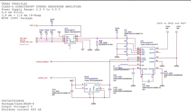
Dear Mr/Mrs. It might be me but I find the datasheet for TPA6141 somehow ambiguous in regards to its recommendations for AGND and SGND. I am using the TPA6141 in a mono single-ended configuration. See page 3 in attached schematic.
 
  • In the description on page 1 of the datasheet it says that INL+ should be connected to ground. But in figure 26 it indicate that it shall be done through a capacitor.
  • Second question is to which ground the INL+ should be connected to.
    • The symbol in figure 26 indicate it is SGND.
    • On page 12 in datasheet(ground sense function) it says that it reduces noise if SGND is connected to different ground reference than codec and amplifier
    • Also in functional block diagram on page 2 it indicate that SGND should be connected to AGND 
Could you please confirm that
  • INL+ shall be connected to a GND through a capacitor as indicated in fig. 26
  • The GND which INR+ is connected to in fig 26, is this SGND or AGND?
  • Should Codec in fig. 26 be referenced to AGND or SGND?

Br Mark

  • Hi Mark,

    I'll take a look at you questions and give further comments shortly.

    Best regards,
    -Ivan Salazar

    Applications Engineer

  • Hi Mark,

    I'm adding some answers below:

    • INL+ shall be connected to a GND through a capacitor as indicated in fig. 26
      • Yes, use a capacitor for this GND connection
    • The GND which INR+ is connected to in fig 26, is this SGND or AGND?
      • This should be AGND, then AGND and SGND should be shorted together at one point
    • Should Codec in fig. 26 be referenced to AGND or SGND?
      • AGND, basically the same GND as the amplifier itself

    You can find some more details information about SGND and ground loop theory on this document: http://www.ti.com/litv/pdf/sloa143

    Best regards,
    -Ivan Salazar
    Applications Engineer

  • Dear Ivan

    Thanks for reply. 

    Can get you to look once more at fig. 26 in datasheet.

    We agree that the symbol connected on this INL+ and the capacitor(1uF) attached to INR+ is the same as the symbol used for SGND(Not GND and in same figure)

    To me it look like the connection needed here is to SGND and not GND(AGND in our design)? I agree that GND and SGND should be attached in one point using 10-20 ohm resistor according the doc./link you attached but that is actually not direcly shown in the datasheet(This might be common knowlegde for all working with audio circuits like this and could be reason why this illustration is not visible in the datasheet?).

    But again - back to the question.  Are there a mismatch between illustration of GND/ reference symbols in fig 26? Should those symbols connected to INL+ and the 1 uF cap have been the GND symbol and not the symbol used for SGND as illustrated in fig. 26.

    Br Mark

  • Hi Mark,

    I found some old reference about the same SGND/AGND question, I'll add it here:

    Connect the input cap to SGND because internal the INx+ resistors for the differential gain references SGND, not GND and SGND is connected to GND through diodes. 

    Best regards,
    -Ivan Salazar
    Applications Engineer

  • Dear Ivan -Thanks for your reply.