


Other Parts Discussed in Thread: PCM1863
Hello,
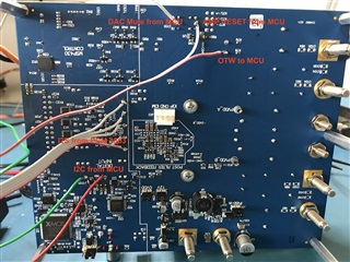
I am trying to use the TAS3251EVM in slave configuration with an external PCM1863 ADC as I2S Master and I2C from an external MCU.
Unfortunately I can not get any sound out of the EVM.
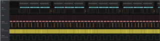
I attached the external I2S 4-wires from the PCM1863 directly to the test-points between the heatsink and the J9 external board connector and can read them correctly with a logic analyzer.
I2C from my MCU is directly connected to the SCL and SDA test-points on the EVM. I checked the I2C data with a logic analyzer and all the registers seem to be set correctly.
The board is set up as follows:
1) J35 is set ( Slave Mode)
2) J19 isn't set (Adress 0x96 or 0x4B)
3) J3, J4, J6, J7 are set to EXT
4) J9 is set to SDIN
5) J37 I2S Select is not set (AIB I2S)
6) J22 is set to Master Mode
7) J33 is not set (XMOS disabled)
8) R54 and R55 are removed (I2C is coming from my PIC MCU)
9) S1 (DAC Mute) and S3 (Amp Reset) are set to normal and connected to MCU for control over startup sequence.
MCLK is 12.29 Mhz, LRCLK is 48kHz, BCLK is 3.07MHz.
At the output terminals I can read the 600 kHz switching frequency. My input signal is a 1kHz sine wave.
Am I missing something ? Please advice me.
Best regards
Here is the register configuration (from PPC3) and code I am using and the start-up sequence:
cfg_reg registers[] = {
//program memory
    { 0x00, 0x00 },
    { 0x7f, 0x00 },		//Switch to Book 0
    { 0x02, 0x11 },		//PowerDown DSP. Bit 0 not documented
    { 0x01, 0x11 },		//Reset module & registers. Bits are auto cleared
    { 0x00, 0x00 },		//Wait
    { 0x00, 0x00 },
    { 0x00, 0x00 },
    { 0x00, 0x00 },
    { 0x03, 0x11 },		//Mute L&R
    { 0x2a, 0x00 },		//Zero Data path L&R (= mute...)
    { 0x25, 0x18 },		//Ignore MCLK error detection
    { 0x0d, 0x00 },		//Clck config..
    { 0x02, 0x00 },		//Wake up DSP
//Sample rate update
    { 0x00, 0x00 },
    { 0x7f, 0x00 },		//Switch to Book0 ... again
    { 0x02, 0x80 },		//Reset DSP
    { 0x00, 0x00 },
    { 0x7f, 0x00 },		//Switch to Book0 ... again
// speed 03-48k 04-96k
//dynamically reading speed
    { 0x22, 0x03 },		//Set FS Speed. Ignored in auto clock mode
    { 0x00, 0x00 },		//Switch to Book0 ... again
    { 0x7f, 0x00 },
    { 0x02, 0x00 },		//Restart DSP
//write coefficients of various components
    { 0x00, 0x00 },		//Switch to Book8c
    { 0x7f, 0x8c },
    { 0x00, 0x1e },
    { 0x44, 0x00 },		//Vol to 0dB
    { 0x45, 0x80 },
    { 0x46, 0x00 },
    { 0x47, 0x00 },
    { 0x48, 0x00 },
    { 0x49, 0x80 },
    { 0x4a, 0x00 },
    { 0x4b, 0x00 },

//swap command
    { 0x00, 0x00 },
    { 0x7f, 0x8c },		//Switch to Book8c
    { 0x00, 0x23 },		//Goto Page 23
    { 0x14, 0x00 },		//Write 00 00 00 01 in reg 0x14+
    { 0x15, 0x00 },
    { 0x16, 0x00 },
    { 0x17, 0x01 },

//register tuning
    { 0x00, 0x00 },
    { 0x7f, 0x00 },		//Switch to Book0
    { 0x00, 0x00 },
    { 0x07, 0x00 },		//SDOut is post processing output
    { 0x08, 0x20 },		//SDOut is output. No mute from PCM
    { 0x55, 0x16 },		//SDOut mux selector - DSP Boot done
    { 0x00, 0x00 },
    { 0x7f, 0x00 },		//Switch to Book0
    { 0x00, 0x00 },
    { 0x3d, 0x24 },		//Digital volume Left	-18dB
    { 0x3e, 0x24 },		//Digital volume Right
    { 0x00, 0x00 },
    { 0x7f, 0x00 },		//Switch to Book0
    { 0x00, 0x01 },		//Switch to Page1
    { 0x02, 0x00 },		//Analog Gain set to 0dB
    { 0x06, 0x01 },		//Analog mute follows digital mute


//Unmute the device
    { 0x00, 0x00 },		//Switch to Book0
    { 0x7f, 0x00 },
    { 0x03, 0x00 },		//UnMute L&R
    { 0x2a, 0x11 },		//Enable data path (L-L & R-R)

};


void init_registers(cfg_reg *r, int n)
 {
    int i = 0;

    while (i < n) {
        switch (r[i].command) {
        case CFG_META_SWITCH:
            // Used in legacy applications.  Ignored here.
            break;
        case CFG_META_DELAY:
            __delay_ms(r[i].param);
            break;
         case CFG_META_BURST:
             I2C1_Send_PA((unsigned char *)&r[i+1], r[i].param);
            i +=  (r[i].param + 1)/2;
            break;
        default:
            I2C1_Send_PA(r[i].offset, r[i].value);
            break;
        }
        i++;
    }
 }


void PA_startup_sequence()
{
    reset_sequence();

    __delay_ms(50);

    init_registers(registers, sizeof(registers)/sizeof(registers[0]));

    __delay_ms(400);

    //adjust_volume();

    //Enable the amplifier output stage by setting the RESET_AMP pin high.
    PA_RESET_SetHigh();

    // Enable DAC
    PA_DAC_MUTE_SetHigh();

}
void shutdown_sequence()
{
  //code for shutdown_sequence
    PA_RESET_SetLow();
}

//code for fault_sequence
void fault_sequence()
{
  // Wait until system temperature gets back to normal temperature: /CLIP_OTW high
  while (PA_OTW_GetValue() == 0)
  {
    __delay_ms(100);
  }
  PA_RESET_SetLow();
  __delay_ms(10);
  PA_RESET_SetHigh();
}

void reset_sequence()
{
  PA_RESET_SetLow(); // Set Amp reset pin low
  PA_DAC_MUTE_SetLow(); // Set Dac mute pin low
}

