Hello, Somebody help me.
I followed procedure in datasheet and set pcm6020 register like this. (i2c dump)
- Sleep -> Non sleep
- Power-up the ADC, MICBIAS, and PLL by writing P0_R117
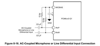
- AC coupled, differential
and removed line (mic to input IN1P IN1M)
but There is still noise in the recorded file.
Should I change another register to remove noise??
Any other tips that aren't in the datasheet?
Dump chip 0x48 on bus 7? (Y/n):y
0 1 2 3 4 5 6 7 8 9 a b c d e f 0123456789abcdef
00: 00 00 01 00 00 05 00 30 00 00 00 00 01 02 03 04 ..?..?.0....????
10: 05 06 07 01 48 48 10 10 04 20 02 08 00 00 02 40 ????HH??? ??..?@
20: 00 22 00 00 00 00 00 00 00 ff 03 00 c8 00 00 00 .".......??.?...
30: 00 00 00 00 00 00 00 00 ba 4b 10 d0 00 00 c9 80 ........?K??..??
40: 00 00 00 c9 80 00 10 00 c9 80 00 10 00 c9 80 00 ...??.?.??.?.??.
50: 10 00 c9 80 00 10 00 c9 80 00 00 00 c9 80 00 00 ?.??.?.??...??..
60: 00 c9 80 00 00 37 87 b8 00 00 00 01 48 7b 00 00 .??..7??...?H{..
70: e7 00 00 fc c0 e0 c0 f8 00 00 ff 00 ff 92 d3 00 ?..?????..?.???.
80: 00 00 00 00 00 00 00 00 00 00 00 00 00 00 00 00 ................
90: 00 00 00 00 00 00 00 00 00 00 00 00 00 00 00 00 ................
a0: 00 00 00 00 00 00 00 00 00 00 00 00 00 00 00 00 ................
b0: 00 00 00 00 00 00 00 00 00 00 00 00 00 00 00 00 ................
c0: 00 00 00 00 00 00 00 00 00 00 00 00 00 00 00 00 ................
d0: 00 00 00 00 00 00 00 00 00 00 00 00 00 00 00 00 ................
e0: 00 00 00 00 00 00 00 00 00 00 00 00 00 00 00 00 ................
f0: 00 00 00 00 00 00 00 00 00 00 00 00 00 00 00 00 ................
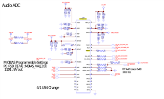
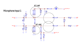
schematic