This thread has been locked.

If you have a related question, please click the "Ask a related question" button in the top right corner. The newly created question will be automatically linked to this question.

INA134: Peak in frequency response

Part Number: INA134
Other Parts Discussed in Thread: INA1651, INA1650

Hello,

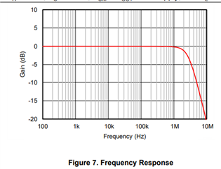
Looking at the INA134 datasheet it shows that the frequency response has a 2-3dB peak at 2MHz, which is also observable when measuring in real life.

What is the standard way of nulling this peak without compromising input CMRR?

I'm curious as to why this product is designed this way, I assume the reduced phase margin must be a design decision based on listening tests rather than measured performance?

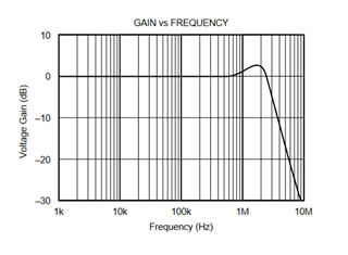
Thanks for any insight..

  • Habibi,

    What is the output of the INA134 connected to in your application? Does the INA134 see a high impedance load or low impedance? If it is high impedance then a simple low pass filter on the output could be used. This peak is in the un-audible range however and wouldn't be possible to hear in a listening test above 20kHz. The INA134 has great distortion and slew rate specs and these trade offs are made during the design process. The slew rate and bandwidth are related through the full power bandwidth and the interconnection of achieving high quality THD specs is considered. 

    Best Regards, 

    Chris Featherstone

  • Thanks for responding, Chris.

    The load is high impedance and there is a 300kHz LPF that feeds a high bandwidth amplifier CFA. The issue I have is that this peaking occurs at the unity loop gain frequency of the amplifier, which causes stability issues. I expect it is just not the correct device for my application.

    Out of interest do you have measured gain and phase margin values for the INA134?

    Thanks

  • Habibi,

    I will take a look to see what data I can pull up on the INA134. This may be a challenge given the age of the device but I will see what I can dig up. In the mean time, have you considered the modern INA1650 or INA1651? It has significantly lower noise than the INA134. In addition the peak that exists in the INA134 doesn't exist in the INA1650. There is even an integrated buffered mid supply output which can be used to bias up the whole circuit to mid supply on a single supply setup. If this device is of interest I can also help you with it. 

    https://www.ti.com/lit/ds/symlink/ina1651.pdf?ts=1658946437177&ref_url=https%253A%252F%252Fwww.google.com%252F

    Best Regards, 

    Chris Featherstone

  • Habibi,

    To follow up on the INA134 phase margin, I have simulated the step response in order to approximate the phase margin. 

    The percent overshoot is:

    P.O = (15.9mV-10mV)/20mV *100% = 29.5%

    A percent overshoot of 29.5% corresponds to a phase margin of approximately 40 degrees. Please ignore the step response in the slide below. 

    With a capacitive load of 100pF I see around 30.1% of overshoot corresponding to around a little under 40 degrees of phase margin. This simulation closely matches the step response seen in the product datasheet. 

    Best Regards,

    Chris Featherstone

  • Hi Chris,

    Thanks for taking the time to put that together, definitely good information to have moving forward.

    I have seen the INA1651 and was planning on using it, or at least having a footprint for it on the board. In the current climate it seems sensible to have a few options, so the SO8 footprint was attractive so I could also use THAT Corp parts etc - when I first started this project/job INA134 was actually out of stock globally, looks like it is coming back now though. I am slightly weary about having a single option (INA1651) as it is a different package, just in case the same happens. Odd times...

    Thanks for your help