This thread has been locked.

If you have a related question, please click the "Ask a related question" button in the top right corner. The newly created question will be automatically linked to this question.

LM4871: Input Impedance

Part Number: LM4871
Other Parts Discussed in Thread: TPA6211A1

Dear TI team,

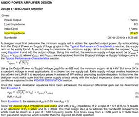
I need to know the amplifier's minimum and maximum input impedances because I plan to work on an LM4871 audio amplifier.

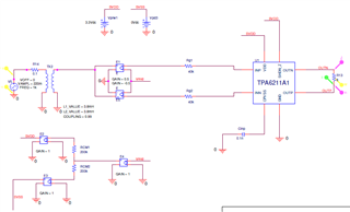
The schematic and DC resistance of the audio transformer we are going to use as input are shown below:

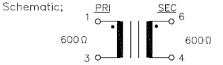
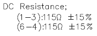
As I will provide the transformer output to the amplifier's input.

Therefore, may it be used to drive the transformer output and play the mp3 file ?

Thanks and Regards

Divyanshu Shukla

  • Hi Divyanshu,

    Proper selection of external components would determine the input impedance of amplifier designed using LM4871. AUDIO POWER AMPLIFIER DESIGN section of datasheet (page 12) provides guidance on external component selections based on design parameters.

    Regards,

    Atiq

  • Dear Atiq,

    Thanks for your feedback. We would want to power the amplifier using the Audio Isolation Transformer TTC-5023, whose primary and secondary impedances are each 600 ohm, and whose DC resistance is each 115 ohm. Will driving the amplifier and getting the output be acceptable, or will you recommend something else?
    What kind of speaker ought to be chosen for the same?

    The Input for the amplifier would be differential input not the single ended input, so we need Differential audio input amplifier, please let me know.

  • Hi Divyanshu,

    Apologies for the delay, within 24 hours a TI expert will be able to help answer your question.

  • Hi Divyanshu ,

    What does the whole system looks like? Perhaps you can add a block diagram to better understand what is the transformer used for?
    The input impedance would depend on your Ri, usually input impedance is in the order of tens-kOhms.

    This device has TINA and PSpice models available in its product folder, you may be able to run some simulations if needed.

    Best regards,
    -Ivan Salazar
    Applications Engineer

  • Hey Ivan,

    Thank you for the comments. I did download the models and utilise them with the audio transformer; the simulation's circuit schematic is shown below.

    The differential mode of the audio amplifier is what we wish to use. Is it therefore compatible with that?

    How does Ri affect the input impedance? Please provide more detail using an equation or something.

    Best Regards,

    Divyanshu Shukla

  • Divyanshu,

    In the data sheet "AUDIO POWER AMPLIFIER DESIGN" section there is an example to set input impedance as 20k, and later on it is mentioned to set Ri=20k:

    I'm not clear on the differential mode of the amplifier you mentioned. This device is a single-ended input and differential output amplifier, if your input signal is single-ended then you may not need the transformer; if your input signal is differential and you're looking for fully differential (input and output) amplifier, perhaps you should consider other devices like TPA62xxA1 family. Your input signal from the simulation is single-ended, so I'm not sure if that's what you're actually looking for.

    Best regards,
    -Ivan Salazar
    Applications Engineer

  • Ivan,

    Since my application requires driving the amplifier through an audio transformer, I cannot remove the audio transformer. Instead, the input from the audio transformer will go to the amplifier and I've selected TPA6211A1DGNRG4 , and we must choose the speaker for the same. As a result of your response, my problem with the single ended has been resolved, and I now understand that the TPA62xxA1 family can be used.

    Would it be preferable to use the TPA6211A1 evaluation board?

    I have simulated the circuit below, and I also want to choose a speaker that can be heard up to a distance of 2 m.

    Kindly help me with the aforementioned.

    I am getting output as V=1.76V, I=28 mA, P= 1.76 W after simulation at RCM1 = RCM2 = 200k Ohm and here the R13= 8 Ohm

    Should I change the R13 to 3 Ohm or 4 Ohm ?

    Best Regards

    Divyanshu Shukla

  • Hi Divyanshu,

    I would suggest to test with an EVM and your actual speaker to better understand the SPL response. Reducing the speaker load R13 would increase the amount of power, although you may want to double check it doesn't lead the output signal to saturate.

    Best regards,
    -Ivan Salazar
    Applications Engineer