This thread has been locked.

If you have a related question, please click the "Ask a related question" button in the top right corner. The newly created question will be automatically linked to this question.

DRV632EVM: UVP pin

Part Number: DRV632EVM
Other Parts Discussed in Thread: DRV632, DRV603

Hi team,

Here're 2 questions from the customer may need your help:

1) Regarding the UVP pin of DRV632PWR which is to prevent chip POP:

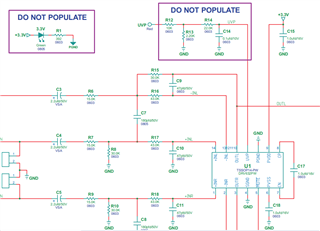
Below diagram is an application diagram of the demo board used to test the UVP pin. With no MCU in hardware mode, can the UVP pin be left floating and not connected to any device?

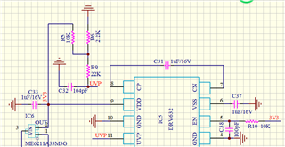
2)  What frequency does the DRV632PWR operate at? For example, the PVDD, PVSS pins of DEMO are all connected to ground through a 1 UF capacitor, and the CN.CP pin is also connected to a 1 UF capacitor. What is the operating frequency?

If they want to adjust this frequency, is it ok to just adjust the capacity of the CN.CP pin? 

Could you help check this case? Thanks.

Best Regards,

Cherry

  • Hi Cherry,

    1) yes if the feature is unused the UVP pin can be left floating - this is OK

    2) the Charge pump of DRV632 operates at 200kHz - 400 kHz, it is recommended to use 1uF capacitor.

    Why does the customer want to change the frequency?

    Regards,
    Arthur

  • Hi Arthur,

    Thanks for your support.

    Why does the customer want to change the frequency?

    Because the signal-to-noise ratio of the DRV632 is high.

    Customer has a 2.1 class D AMPLIFIER and currently wants to use 2 DRV632 for electronic division, LOWPASS is 20Hz-300Hz and high pass is 300Hz-20000Hz.

    In case of differential interference, the operating frequency may need to be changed.

    Also, What is the operating voltage range of VSUP_M0 when the UVP pin is used when the DRV632 is operating at 3.3 V?

    The UVP automatically turns off the device on the principle that the external voltage, VSUP_M0, is divided down by the R1,R2 resistor, that turns off the device when the voltage on R2 is less than 1.25 V, and that turns on the device when the voltage on R2 is greater than 1.25 V. correct? 

    Thanks and regards,

    Cherry

  • Hi,

    May I know is there any update?

    Thanks and regards,

    Cherry

  • Hi Cherry,

    there is not a specified supply range for VSUP_M0, since the voltage will be divided by the resistor network on the UVP pin. It is just import to make sure that the UVP pin is not exposed to voltage above VDD. 

    VSUP_MO is intended to be the supply voltage of the system.

    The resistor divider will depend on the the system. the voltage divider needs to be chosen such that the UVP protection on DRV632 is tripped before other ICs in the system would cause a pop. 

    your understanding is correct about the 1.25V threshold. 

    I am discussing still with the team if it is possible to control the charge pump frequency.

    Regards,

    Arthur

  • Hi Cherry, 

    Another applications engineer has had this same request before. the charge pump frequency cannot be modified, 

    However the device DRV603 is pin-for-pin compatible and has a higher typical charge pump frequency

    Regards,
    Arthur