This thread has been locked.

If you have a related question, please click the "Ask a related question" button in the top right corner. The newly created question will be automatically linked to this question.

TPA2016D2: THD+N specs on the datasheet of TPA2016D2

Part Number: TPA2016D2

There are two questions about audio amplifier TPA2016D2 as follows.

1. Output power [W] versus THD+N [%] curves are drawn on the datasheet of TPA2016D2. Could you let me know the measurement conditions as detailed as possible, including the matter which are not written on the datasheet (e.g. the model number of measuring equipment) ?

2. Can we get the same THD+N curve as the datasheet if we measure the evaluation module TPA2016D2EVM ?

  • Hi,

    Given the time of this device development, most likely the equipment used for test was audio precision 2700 series, but similar performance can be measured with more recent apx500 series.
    Yes you should get similar performance using the EVM, there may be a slight increase in THD due to the LC filter at the output, but you could remove the capacitors and short across the inductors if needed.

    Best regards,
    -Ivan Salazar
    Applications Engineer

  • Thank you very much for your reply.

    Have you used AUX-0025(Switching Amplifier Measurement Filter) with AP2700 when you measured THD+N characteristics?

  • Yes, AUX-0025 is used as well.

    Best regards,
    -Ivan Salazar
    Applications Engineer

  • Actually, I measured THD+N under the following conditions, however the result was 0.25% in minimum. Could you point out what is wrong with my measurements?

    Measuring equipment : APx585 + AUX-0025

    Generator frequency : 1kHz

    Measurement object : TPA2016D2EVM

    Load (resister) impedance : 8ohm

    Power supply : 5VDC

    Fixed gain setting : 6dB

    Output power : 0.73W

    The datasheet says that I should get less than 0.1% under the above conditions.

  • I'll look for an EVM and try on my side. As mentioned, you may need to remove the LC filter at the output.
    I'll get further comments by end of the week, or let you know otherwise.

    Best regards,
    -Ivan Salazar
    Applications Engineer

  • I've been doing some tests on my side and got some relevant information:

    • TPA2016D2 includes some features such as DRC and AGC. When measuring THD performance special care must be taken such that the device does not enter any of these non-linear control features ie. if the signal is being affected by compression, limiter or AGC, the THD reading will be higher than expected.

    Please consider the linear regions displayed along data sheet figures 5 through 9.

    Best regards,
    -Ivan Salazar
    Applications Engineer

  • Thank you for the relevant information.

    I retried the measurement and I got the smaller THD-N than previous measurement, 0.15% at 0.23W Pout. However, this result is still larger than the datasheet.

    I checked the output LC filter on my TPA2016D2EVM, no capacitor has been mounted (C24, C29, C30 and C31 are empty)

    Inductors (L4, L5, L6 and L7) are mounted, but I guess that I don't need to short them because the measurement condition on the datasheet seems to include them.

    The I2C setting parameters are as follows.

    Attack Time : 6.402 msec/6dB

    Release Time : 164.4 msec/6dB

    Hold Time : 0msec

    Compression Ratio : 1:1

    Noise Gate Threshold : 1mV

    Fixed Gain : 6dB

    Max Gain : 30dB

    Limiter : Disable

  • What is your PVDD level?
    Is the gain 6dB as expected? 0.23W should be within the linear region but just want to make sure.
    I'll try to replicate on my side, data sheet suggests ~0.8% so you're pretty close to the expected value.

    Best regards,
    -Ivan Salazar
    Applications Engineer

  • I apologize that my previous information was not enough and included wrong value.

    My PVDD level was 5VDC from stable DC power supply.

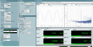
    The output power when I got 0.15% THD+N was NOT 0.23W BUT 0.92W (2.71Vrms on 8ohm resistor)

    At the time, input level was 1.36Vrms, therefore 6dB gain was as expected (20*log10(2.71/1.36)=5.99)

    Under the above condition, the datasheet suggests ~0.09% and my result (0.15%) is still larger.

  • Thanks for adding more details, I'll do the same test on my side, however I think the value you're measuring may be correct already as it's close to the plot.
    I'll update later today or tomorrow after testing.

    Best regards,
    -Ivan Salazar
    Applications Engineer

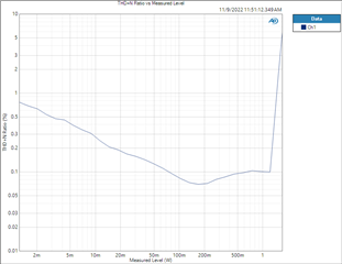
  • Attached is my test result:

    Register settings: c3 05 0b 00 06 ba c0

    Best regards,
    -Ivan Salazar
    Applications Engineer

  • I found the reason why my result was worse than the datasheet. I replaced the 8ohm load (resistor) with the other one, and I got the result similar to yours or the datasheet. I guess that the previous resistor includes helix wire, therefore it has unexpected inductance.
    I'm sorry to have troubled you.

  • It's good to know you're getting the expected results now. Thanks for coming back to close this thread.

    Best regards,
    -Ivan Salazar
    Applications Engineer

  • I'm sorry to visit here again.

    Could you measure THD+N under the following conditions and give me the result?

    Measuring equipment : APx585 + AUX-0025

    Generator frequency : 1kHz

    Measurement object : TPA2016D2EVM

    Load (resister) impedance : 4ohm

    Power supply : 5VDC

    [I2C settings]

    Attack Time : 6.402 msec/6dB

    Release Time : 164.4 msec/6dB

    Hold Time : 0msec

    Compression Ratio : 1:1

    Noise Gate Threshold : 1mV

    Fixed Gain : +12dB

    Max Gain : 30dB

    Limiter : Disable

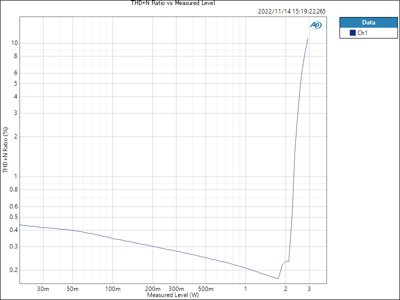
    And could you refer to the attachment (my result under the above conditions)?

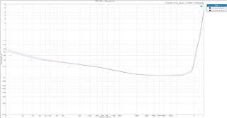
  • I tested on my side for two different configurations:

    • Register settings: c3 05 0b 00 06 ba c0  (6dB fixed gain)
    • Register settings: c3 05 00 00 0c 9a c0  (12dB fixed gain)

    Unfortunately there is no clear comparison vs data sheet plot, as the only THD+NvsPout @ 4-Ohm is spec for "QFN only".

    You may double check the resistor you're using for measurement has proper current/power rating. You may also add an inductor in series to match the usual test load 4-Ohm + 33uH, if not using it already.

    Best regards,
    -Ivan Salazar
    Applications Engineer