This thread has been locked.

If you have a related question, please click the "Ask a related question" button in the top right corner. The newly created question will be automatically linked to this question.

TLV320ADC5120: How to disable Digital Mixer?

Part Number: TLV320ADC5120

Hi!

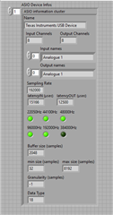
I believe digital mixer is preventing me from sampilng at 384KHz- please let me know if I am fixating on the wrong thing! I am hoping to get a 384KHz sample rate with DECI_FILT = 10 (ultra low latency). I’ve been able to get this setup working on 2 channels at 32 bit word length and at 192 kHz but I haven’t been able to get up to 384 kHz

In section 3.5 of app note, AGC, DRE, DRC, bi-quads, channel summers, and digital mixer processing blocks are not supported for 384 kHz operation  https://www.ti.com/lit/an/sbaa494a/sbaa494a.pdf 

From my understanding, CH_SUM[1:0] must be 00. However, table 2-5 mentions [00] = Channel summing mode is disabled (Digital Mixer is enabled).

Would this prevent me from getting desired 384KHz? Anything else to look at?

Thank you,

Cameron  Wutzke

  • Update: I noticed ASI_STS register show the auto-detected sample rate of ASI bus is 192KHz- could this be the debugging path to pursue? Maybe explains why 192KHz works but 384 does not 

  • Hi Cameron, 

    Yes it is a good starting point for debugging, is device in master or slave mode? How did you configure MST_CFG0 Register, 0x13, & MST_CFG1 Register, 0x14?

  • Hey Daveon,

    I attached registers here- i2c_registers.csv

    MST_CFG0 = 0x02 

    MST_CFG1 = 0x48 

  • Customer ran another test and believes it could be issues with the way they drive the device rather than with any device level configuration.  They're looking through dll files- I pasted below for flavor

    (Adding customer's feedback- apologies for word dump)

    Per your suggestion, I’ve enabled ASI_ERR.  If device is running at a supported sample rate such as 48 kHz and I read register 0x36 (int_ltch), there are no interrupts.  If I change the frequency from 48 kHz to 192 kHz and then re-read the register, the PLL LOCK bit (bit 6) is flipped which makes sense given the PLL would have unlocked and relocked during the frequency transition.  If I then change the frequency from 192khz to 384khz and re-read the register, the only bit flipped is still the PLL LOCK bit.  As a test, I set the device to 48 kHz and then switched from 48 kHz to 384 kHz and then read the INT_LTCH0 register and it returned all 0’s.  This also seems consistent with the previous behavior given the device seems to default to 48khz when it is commanded to a frequency which it appears to not support. 

    A few other notes… In the user manual for the eval platform there were some references to a matlab program that would set the sample rate of the device.  I don’t have access to the audio toolbox so I’ve been using a labview API that allows me to communicate with audio devices using ASIO drivers.  Within this API there is a function that allows me to request device information and when requesting this information it states that 384 kHz is not supported (see below).


    Unfortunately, I’m not completely sure what information the labview program is receiving to arrive at this determination because this function is centered around a dll call and I don’t have much visibility into what the dll is doing.  It does appear that the dll is calling functions from the winmm.dll so I’m going to see if I can understand what functions are available within the winmm.dll that I could just call directly in hopes that removing 1 layer of abstraction may help me either understand what is happening and/or resolve the underlying problem.  A bit of an aside but as you can see in the image, 44.1khz appears to be supported but multiples of this are not.  I’ve tried setting the device to 44.1 khz and 88.2 khz – 44.1khz worked as expected and 88.2khz did not.  I’m inclined to believe this is due to the functions available in .dll that labview is calling rather than due to device limitations and that is probably not related to my inability to drive the device at 384khz given the labview function appears to support 384khz but I still hope to be able to understand a bit more about what’s happening inside that blackbox in case the issue is due to how I am driving the eval platform instead of how the eval platform is being configured.  I realize a lot of these details probably aren’t completely relevant to you but I just wanted to detail a bit more into how I’m currently communicating with the device in case there is some obvious problem in my setup.

  • Hi Cameron,

    What BCLK are you setting for 48kHz sampling? At 2Ch * 32Bit * 384kHz = BCLK should be 24.576Mhz


    ADC5120_ULL.cfg

    Try these I2C settings with BLCK provided, I recommend downloading PPC3 to help configure your device as well.

  • Hey Daveon,

    Regarding BCLK, I agree that it should be 24.567 MHz but if I understand everything correctly, BCLK is provided from the AC-MB in the EVM.  Currently all I am doing is commanding the eval platform to output data at a specified sample rate at which point I presume the AC-MB is choosing the bclk rate and the rest of the clocks are configured via auto clock configuration.  I currently don’t have any ability to tell the AC-MB what specific BCLK rate to set.  This appears to coincide with the matlab example provided in section 7.3 of the evm user guide.


    I applied the configuration you sent me but it did not appear to work.  I did have a few questions about differences in settings. 

    • Registers 0x0B and 0x0C are both set to 0 which will set both ch1 and ch2 to TDM slot 0.  Was this intentional?
    • Register 0x08 was written to register 0x1F which changes the state of many reserved bits.  Was this intentional?
    • Registers 0x3C and 0c41 were configured as single ended inputs instead of differential inputs.  I assume there is no reason why a differential input can’t be used at 384 kHz?
    • Register 0x6C was configured to enable 1 biquad filter per channel.  Shouldn’t these be disabled to allow for 384 kHz?


    The adc has an internal antialias filter which is a function of sample rate.  Is there any way to disable this completely?

    One last question… does the TI USB Audio 2.0 driver support the 384 kHz sample rate?

  • Hi Cameron,

    Okay, yes I was unaware you were utilizing the EVM. 

    I did have a few questions about differences in settings. 

    I didn't know the setup of your system, please disregard cfg file sent.

    384kHz is supported and should have no issue

    In test setup, I loaded differential mic setup preset, and supplied the clocks below, 5120 PPC3 recognized 384kHz sampling.

    Let me know if you have any questions

    The adc has an internal antialias filter which is a function of sample rate.  Is there any way to disable this completely?

    This is integrated in IC, no way do disable.

    kind regards,