This thread has been locked.

If you have a related question, please click the "Ask a related question" button in the top right corner. The newly created question will be automatically linked to this question.

TAS5806MD: Speaker heat up when ideling

Other Parts Discussed in Thread: TAS5806MD

Hello again,

a stereo amplifier consumes at PVDD = 12V in play mode, when no input signal is present, about 1W power, which is quite a lot.(so 0.5W idle power per speaker) After some time the magnets of the speakers heat up to about 30°. The voice coil is then probably even hotter. How can I reduce this idle current? Why do the loudspeakers get warm? Shouldn't almost no current flow through the speakers when no signal is played?

Modulation frequency: 782kHz
Loop BW: 175kHz
Modulation scheme: BD
Output filter: ferrite bead (NFZ2MSM301SN10L)
PVDD: 12V
Loudspeaker: 3.7 Ohm; 0.07mH


  • Hi 

    as you said, if at idle state, there should be almost no current flow at output.

    can you help confirm what kind of waveform are outputted.

    also, can you confirm whether the chip of the GND been connected together or not.

    and the thermal pad, is it been soldered well.

    thanks.

    jesse

  • Hello

    what do you mean by the waveform output?
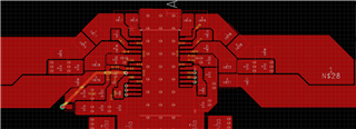
    As far as I understand: since it is idle, there is no signal, so the waveform is just a straight line at 0V. The thermal pad is well soldered and the GND is connected as stated in the datasheet. The routing looks like this. (note that not all areas are filled in yet, as this is a pattern printed several times on a large 4-layer board) (note also that the idle problem has already occurred on boards with only one amp IC).


    Are there any settings I need to change in the registers of the TAS5806MD? Did you already have similar problems like this with another IC? What do you suspect could be the cause? A ground loop? The thing is that the speakers get hot/warm at idle, not the amplifiers! So I'm sure that the amplifier is somehow putting out a current of about 0.35 amps (0.5~=3.7ohms*(0.35A)^2) to the speakers when there is no input signal (ideling). A conceivable possibility for this would be that the modulation of the amplifier is out of phase and therefore outputs a DC voltage...

  • HI Getzner

    according to your description, it seems like dc was output to the speaker.

    can you help confirm how much DC offset exist at the speaker side?

    also, at idle state, there should be PWM waveform at out+ and out-, can you help check the waveform too?

    we haven't seen this kind of situation at other device.

    you mean only 1 device have this problem at your hand, other devices don't have this problem even using same circuit. am i understanding correct?

    is that possible to perform ABA test?

    remove the chip of failure one to another good PCB to confirm whether the failure mode follow the chip or the board?

    thanks.

    jesse

  • Hi Jesse,

    unfortunately I will not be able to measure this until January as I will not be near the lab for the next 2 weeks. Therefore, I would ask you to give me some time and not to close the thead until then.

    However, I know that this does not only occur with one amplifier, because I have tested this with 20 different TAS5806MD ICs and they all show the same behavior. A-B-A tests were also done and showed no difference in behavior.

    Is there any setting that can be changed to minimize this? Could this also be a common problem with filterless designs?

    Thank you for your help so far.

  • Hi Severin

        This is not a common phenomenon, and in the idle state, there really shouldn't be current into speakers, the settings in the register can't get this results. We have EVM that been using FB as the filter, there shouldn't be problems.

        I think there maybe some other reason for speaker heat up. May I know do you hear any sound from the speaker in the idle state? Because if there's really current flow through speaker, speaker will make sound. If there's no sound, I'm thinking if the common mode voltage changing will cause your speaker heat up. Without filter, there will be common mode PWM waveform send into your speaker. Seems our other customer didn't feedback similar case like your side.

  • Hi Severin

    after you get some waveform, you can open this ticket again anytime.

    thanks.

    jesse

  • Happy new year Jesse! Slight smile

    So these are the waveforms. The line in the middle is the substraction of both waveforms while pink being the negative output and yellow the positive one. (Attention: the voltage is only 5V/divison for the math channel)
    It must be said that changing the switching frequency from 782kHz to 384kHz has already reduced the quiescent current by about 30%, but the result is still not satisfactory.

    This is the output measured at the speaker terminals:

    and this is the output measured directly at the output pins of the IC:


     No sound is coming from the speakers, except the slight audbile noise genereated by the ADC, but I think that is a different topic.

  • Hi Severin

    while using ferrite bead, the ripple seems too large than normal idle state.

    can you help confirm how the speaker temperature change after performing below action:

    1. remove the 2.2uF capacitor to see whether speaker become hot too.

    2. check whether pvdd is stable or not? it seems like your output pwm has so much ripple.

    thanks.

    jesse

  • Hi Jesse,

    you are right, I just measured and indeed the ripple is very large and the PVDD is very noisy, it seems to have captured a lot of noise from the BCLK of the I2S line at about 6.1MHz.. How could I improve this?

    Here it is recorded:
    Yellow: The time base of PVDD referenced to ground;
    Pink: The FFT of the waveform.


    I'm sorry, I don't think I'm quite sure what you mean by 2.2uF capacitor. Do you mean the 2200pF capacitor at the output, the 0.22uF bootstrap capacitor, or the 22uF filter capacitor? I assume you meant the 2200pF capacitor behind the ferrite bead.

  • Hi Severin

    About the noise in pvdd, have you check your GND of power supply, is it been connected together with amp gnd.

    is there any place where GND hasn't been connected together.

    noise in bclk, i think it should be ok if amp can play the sound normally.

    the capacitor i mean is 2200pF capacitor at the output, so sorry for the typo miss.

    thanks.

    jesse