This thread has been locked.

If you have a related question, please click the "Ask a related question" button in the top right corner. The newly created question will be automatically linked to this question.

TLV320AIC3104: PLL Configuration

Part Number: TLV320AIC3104

Dear Sir or Madam,

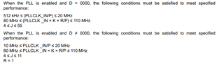
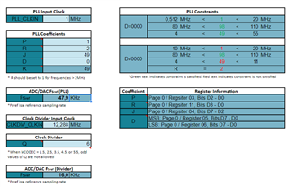
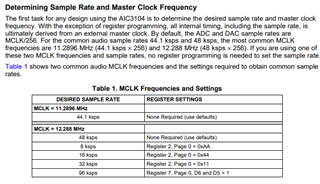
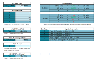
I'm currently using the TLV320AIC3104 and I'd like to use the PLL in order to generate the Audio Clock. I provide a 512kHz MCLK and I'd like to have a sampling frequency of 16kHz (data width of 16 bits). I don't understand how I am supposed to compute the different coefficients. I tried the xlsx file but still I can't find any matching combination.

Could you explain me how all this work ?

Have a nice day,

Kind regards,

William.

  • Hi William, 

    Unfortunately you would need to provide a higher MCLK frequency. 0.512MHz is already at the minimum allowed CLKIN so P must equal 1. You are then only limited to combinations of K & R to generate the desired frequency and there are no combinations that can satisfy the constraints while achieving 16kHz Fs. 

    With D=0, I could only generate 48k Fs while manipulating coefficients.

    Using the clock divider, you would also have to provide a higher frequency.

  • Hi Daveon,

    Thank you very much for your feedback.

    What would I have to do in order to generate a 16kHz sampling frequency ? I can provide a MCLK of 4MHz maximum.

  • Hi,

    I'm out of office today for US holiday, please be patient as responses are delayed.

    *But I suggest playing around with different MCLK frequencies and coefficients in the .xlsx file, there are several combinations that could work

  • In addition, The benefits of PLL is that if you can't supply common MCLK frequencies you can still achieve your desired Fs. So, I suggest determine what MCLK you are going to supply then manipulate the coefficients in the calculator to achieve 16k Fs

  • Hi, thanks for the tips.

    I wanted to provide a 1MHz MCLK but I didn't managed to modify the register in order to satisfy all the satisfactions and getting an Fs of 16kHz. I had a "good" combination for an Fs of 48kHz. I'll try more combination in order to get 16kHz

    My other question is, what is the purpose of this Fs ? Because, apparently, it is possible to divide by an ADC/DAC divider in order to define theirs sampling frequencies (in my case I could divide it by 3 then ?). And the sampling frequency of the I2S is fixed by the master I think.

    Have a nice day,

    William.

  • Hi,

    You only use the PLL in AIC3104 if you don't have a standard MCLK (Figure 1). The block diagram shown in the .xlsx tab highlights two routes possible for achieving your desired Fs. You can use the clk divider or PLL. For example, If you can supply 4.1MHz MCLK, you can use clock divider with Q=2 to achieve 16kHz Fs. 

    Figure 1

  • Okay, I think it is clearer to me now. I still have one misundertanding about all those clocks. What is the real purpose of Fs ? Because even if I can't provide a MCLK of 4.1Mhz, I still could provide a 1Mhz for example. Then my PLL would make a fs of 48kHz. But independantly I can have an ADC/DAC sampling frequency of 16kHz and an I2S sampling frequency of 16kHz too. 

    Have a nice day,

    William.

  • Hi William,

    I may not be fully understanding your question, but as the sampling frequency increases so does the resolution of the audio output. You are sampling your audio frequency more times per clock cycle as Fs increases. Lower sampling frequencies also require less processing so for example if there is an audio application that would like to only playback a 1kHz tone having a lower sampling rate is all that is necessary.

    Also, please note that the audio bandwidth is Fs/2 and most streaming music is played within 18kHz<x>24kHz range, hence common 44.1/48kHz Fs.

    Ultimately, Fs can be anything the user desires so as long the clocks are provided to support it.

  • I do understand the purpose of Fs but the difference between Fsref and Fsadc/dac is still ambiguous.

    For example on the excel sheet, Fsref can be any value : 

    But on the component datasheet it seems that Fsref can only be 44.1kHz or 48kHz (up to 53kHz in particular cases)

    How can I then be sure of the value of Fsref and Fs adc/dac fixed in the component.

    Kind regards,

    William.

  • Hi William,

    Sincere apologies, I was misunderstanding and giving advice based on wrong device flow. For TLV320AIC3104, in the excel sheet whether you use the PLL or divider you want the Fs(ref) to be 44.1kHz or 48kHz based on the source clock you provide. The sampling rate the user wants can be derived from Page 0, Register 2: Codec Sample Rate Select Register.

    For example with 0.512kHz MCLK, [P,R,J,D]=[1,6,32,0], Fs(ref) =48kHz.

    To achieve 16Khz sampling, you set pg0, register 2 : 0x44.

    This should solve your issue.

    Regards