This thread has been locked.

If you have a related question, please click the "Ask a related question" button in the top right corner. The newly created question will be automatically linked to this question.

TPA3244: Gain

Part Number: TPA3244
Other Parts Discussed in Thread: TPA3245

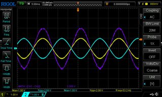
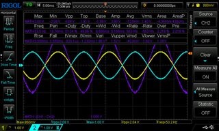
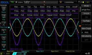
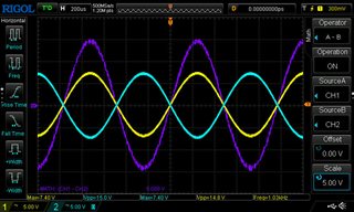
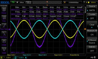
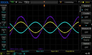
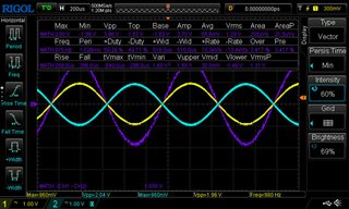
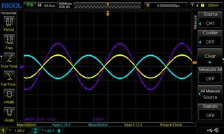
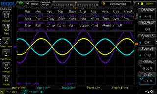
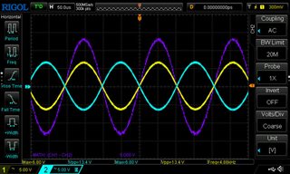
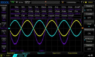
Hi. I'm using the TPA3244 in a design and I saw that the gain is given as 20dB in the datasheet. I measured it (differentially) and I can't get more than 18dB, which coincidentally is the same as the TPA3245. Could you confirm that the 3244 actually has 20dB gain, and if so, why I am only measuring 18dB

Many thanks

Santo Prattico

  • Hi Prattico

    can you tell me what board you used for measuring the gain?

    and more detail about you measuring method?

    BTW, this problem you find on 1 chip or all chips have this problem?

    thanks.

    jesse

  • Hi Jesse,

       many thanks for your kind reply.

    Basically, I measure what is on the inputs differentially (using two channels of a digital oscilloscope and the math function to obtain the sum of the two inputs - I don't have a differential probe yet), then I measure the output of the amplifier in the same way, but with an 8 ohm resistive load .The amp has an LC filter (7uH and 100n) and purely for measurement purposes, there is RC filter (100 ohms + 47n to ground) connected on each side of the load. 

    Whatever signal goes into the TPA3244, the signal I measure on the output is exactly 8 times bigger, i.e.18dB. I have tested 10 amplifiers and they are all like this. I bought the TPA3244 directly from the TI online shop and they work fine, except for this gain matter. 

    I understand that the TPA3244 is the same as the TPA3245, except that it is pad-down instead of pad-up. Coincidentally, the TPA3245 is shown as having a gain of 18dB, not 20dB. I am wondering if the 20dB gain shown in the TPA3244 datasheet is actually a mistake (there were other mistakes in the same datasheet which I reported some time ago and that have been corrected).

    I have no problems if there is a mistake in the datasheet and the gain is actually 18dB, but I just need to know it so I can adjust the gain levels in my design.

    Many thanks

    Santo

  • Hi Santo

    Sorry for confusing you.

    if possible, could you share me the input/output waveform?

    for our side don't have this EVM board at hand currently, we will try to get a board and confirm this issue.

    thanks.

    jesse

  • Hi Jesse, sure, no problem.

    The images show a 50Hz sine wave measured across the inputs of the 3244 and the outputs (yellow and cyan) measured after the 7uH+1uF output filter with a 4 ohm load (there is also a 100R + 50n filter for measurement, but the values are the same before and after this filter). The purple wave is the math feature of the oscilloscope to simulate a differential measurement.

    I measured 1.38-1.4Vrms on the input and approx 11V on the outputs (there is a little variability), giving approx. 8x gain, i.e. 18dB.

    Input without math values 

    Input with math values

    Output over 4ohms without math values

    Output over 4 ohms with math values

    I hope this is useful.

    Regards

    Santo

  • Hi Santo

       I think the problem may caused by the frequency 50Hz. For analog input device, the DC block capacitor at the input port always create a low pass filter with the port input impedance. How about try testing with 1KHz?

  • Hi Jesse. I am actually making the measurement of the input signal after the DC blocking caps, so it shouldn't make any difference: I believe that I should see on the outputs simply the input signal x the gain of the 3244.

    I also tried different freqeuncies and the ratio is always the same, but later today I will try again at 1kHz and send you the images.

    Kind regards

    Santo

  • Sorry Shadow, I thought it was still Jesse!

  • Hi Shadow,

       here are the tests you requested at 1kHz. I also did them at 4.5kHz. The values are a little approximate due to the graphics of the oscilloscope, but you will find that the gain on both is between 7.5x and 8x (18dB). As I mentioned before, the measurements of the input signals are made after the DC blocking capacitor, whereas the output measurements are taken directly from the load resistor because the 100R/47n measurement filter caused the higher frequencies to reduce (fc = 31.5kHz).

    By the way, I made the same measurements on an 8 ohm load, and the results were more or less the same.

    Regards

    Santo

    Input without values, 1kHz

    Input with values, 1kHz

    Output on 4 ohms without values, 1kHz

    Output on 4 ohms with values, 1kHz

    Input without values, 4.5kHz

    Input with values, 4.5kHz

    Output on 4 ohms without values, 4.5kHz

    Output on 4 ohms with values, 4.5kHz


  • Hi Santo

      Indeed your waveform seems no problem. But I also try to search the material left for this device, didn't find the evidence that the Gain shold be 18dB. Sorry for limited resource for old devices. I think we could say the device works fine, shouldn't cause trouble.

  • Dear Shadow,

       thanks for confirming that my measurements are correct and for searching for material. I am quite surprised though that the manufacturer of the device is unable to confirm whether the datasheet is correct. The device itself is shown as active on ti.com so it should be supported, however old it is (we wouldn't use NE5534s is we followed that train of thought!). As it is an active device, we designers will buy them and we depend on the information in the datasheet to be correct to get our designs correct and on the market in a timely fashion. I know that the device works in my design (three of them are being used in a powered speaker that we are already late in launching), but the difference between the 20dB and 18dB gain is the difference between a product that potentially clips if I design it for 18dB, or has low power if I design it for 20dB. I think it's in TI's interest to make sure that the information in the literature is correct. Is there nobody in your organization that knows the TPA3244, has an EVB and can take 20-30 minutes to inject a known signal in and measure the resulting output signal? Thank you.

  • Hi Santo

       I agree what you said, it's just the things may not always that simple. There always many organization change along the time going. The problem for the old device, is they are likely to be combined from other production group, which is already disappeared from organization structure. The designer and planer for these devices, may also left TI long time ago, sadly we don't know any of them. We could only try to find out the answer from the material left for these device, but they may not include everything.

      But we will continue giving you support since this device belong to our production line, for now. I already request EVM sample internally, and may arrive to our side for one or two week. Also these two week happens to be the National Holiday at our side. We will check the Gain value, after we got the EVM board. Will let you know as soon as we can, thank you.

  • Hi Shadow, no worries, I'll wait for your feedback. In the meantime, 新年快乐! (I used to live in 深圳...) Have fun!

  • Hello Santo,

    Inverting voltage Gain says 20dB but it should be 18dB. Was something in the pipeline for datasheet corrections for this device. Sorry for the confusion. The expected gain is 18dB

    best regards,

    Luis

  • That's excellent, many thanks Luis. Take care.

    Kind regards,

    Santo