Because of the Thanksgiving holiday in the U.S., TI E2E™ design support forum responses may be delayed from November 25 through December 2. Thank you for your patience.

This thread has been locked.

If you have a related question, please click the "Ask a related question" button in the top right corner. The newly created question will be automatically linked to this question.

TAS2555: Output Clipping, PWM outputs not at VBoost

Part Number: TAS2555

Hello

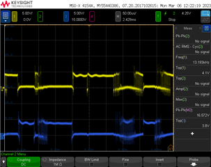
I am trying to increase my output amplitude but my output waveform is clipping.  I have included an image of the desired waveform (green waveform) with Speaker Control register setting of 0x3C but if I increase above 0x3C (like 0x7C waveform (green) attached), the peaks of the waveform are clipping.  I show VBoost too (yellow trace) and it looks to be at a correct level.  Should the speaker PWM outputs be ramping up closer to the VBoost level at the points where my output is clipping (I measure PWM outputs at 5-6V)?  Are there other things to investigate as to why the output would clip above speaker control gain setting of 0x3C?  PWM outputs feed a step up transformer and then green output waveform is measured across a 500 ohm load.  Can you suggest a way to demonstrate I have my TAS2555 configured to achieve maximum output power?

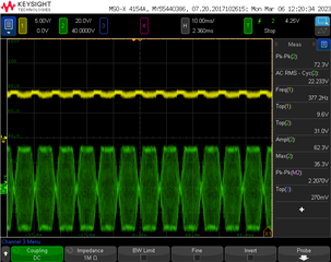
Desired output waveform with speaker control 0x3COutput waveform clipping at speaker control 0x7C.  VBoost is yellow trace.PWM outputs around 5-6V peak

  • Hi Brad,

    The output should be switching closer to the boost voltage at higher signal levels. Can you try without the load connected at the output? I'd like to check if this could be a current limitation.
    What is the load impedance?

    Best regards,
    -Ivan Salazar
    Applications Engineer

  • Hi Ivan

    As an update on this: I can get the full output amplitude using the TAS2555 eval board driving my load.  What is the best way to export the TAS2555 configuration register settings from Pure Path Console so I can duplicate them in our embedded design?  I tried End System Integration -> Dump the Binary file and see that exported several .cfg files.  Would I have to take the content from all of these .cfg files in the order they were generated to create a single stream of I2C register writes?  Do I just need to use some of the .cfg file content?

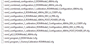
  • These are the .cfg files that were exported.

  • Hi Brad,

    You should be able to initialize the device using only the first cfg file '...combined_configuration_0_...'
    Could you please try this and let us know if having any trouble?
    Thanks

    Best regards,
    -Ivan Salazar
    Applications Engineer