This thread has been locked.

If you have a related question, please click the "Ask a related question" button in the top right corner. The newly created question will be automatically linked to this question.

PCM1794A: THD+N and SNR improvement

Part Number: PCM1794A
Other Parts Discussed in Thread: TPS65131, , SA5534, SA5532

Hi team,

Here's an issue from the customer may need your help:

Designed with PCM1794A, backend IV SA5532, LPF uses SA5534. The op amp supplies ±12 V (TPS65131+TPS7A4701/TPS7A3301), circuit had referenced the evaluation board, 2.2 Vrms output.

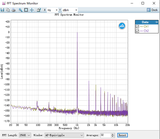
The THD+N does not meet the 192k in the spec, 0.0015%, and the THD either cannot.

Currently 48k is at 0.00065%, 96k-0.0010%, 192k-0.0030%.

1) How to improve THD+N?

2) How to improve the signal-to-noise ratio which currently is only 121 dB?
Could you help check this case? Thanks.

Best Regards,

Cherry

  • Hello Cherry,

    Datasheet only specifies the nominal value and doesn't have a lower limit that i can refer to . Please  note that these numbers are obtained using A-weighted filter and 4.5V rms.

    For THD+N: 20-Hz HPF, 20-kHz apogee LPF  .

    For  Signal-to-noise ratio: 20-Hz HPF, 20-kHz AES17 LPF, A-weighted

    Can you confirm these are the conditions for your measurements, or measure it with these conditions  ( both filter and rms value) ?

    Also are you measuring these numbers at the output of the DAC itself or after the filtering amplifiers which can introduce more distortion or degradation of signal?

    Kind Regards,

    Arash 

  • Hi Arash,

    Thanks for your support.

    Datasheet only specifies the nominal value and doesn't have a lower limit that i can refer to . Please  note that these numbers are obtained using A-weighted filter and 4.5V rms.

    Datasheet has a 2.0 Vrms output, so the customer also outputs 2.0 Vrms.

    Can you confirm these are the conditions for your measurements, or measure it with these conditions  ( both filter and rms value) ?

    Both THD+N and SNR measurements are taken under 20-Hz HPF, 20-kHz apogee LPF, A-weighted.

    Also are you measuring these numbers at the output of the DAC itself or after the filtering amplifiers which can introduce more distortion or degradation of signal?

    The customer has a differential signal at the output of the I/V operational amplifier, measuring with 620R to ground, which is similar to the value of the RCA output after the direct LPF.

    Also how to measure these numbers at the output of the DAC itself?

    Thanks and regards,

    Cherry

  • Hell Cherry, I see. Thanks for confirming  the datasheet condition's on filters and BW of AP. are followed.

    In general to measure the characteristic of a part , we disconnect the additional circuitry from it , as degradation and additional harmonics can be picked up in the path to where we  are measuring. If they can measure the performance  at the output of the I/V circuitry and see any degradation is coming from the filter circuitry , we might get some data point.

    Looking at the obtained numbers  , for example at 96k it is 100dB and datasheet is nominally at  101.9dB , and for 192K it is 90.45dB Vs  96.45 , I am suspicious the layout and routing is picking up additional harmonics. Can they also check and see path is symmetric for both VoutP and VoutN , for example?

    Regards,

    Arash

  • Hi Arash,

    a. The LPF is disconnected when the customer measures the I/V output, and the data is the same as the measurement after LPF.

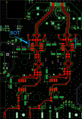
    b. The Layout is limited by film capacitance, etc., and has been made as symmetrical as possible. Please help double check if there's any problem if possible.

    c. Measuring multiple PCBs found that the performance for THD was particularly different. For example, PCB1--THD+N is fully compliant with the specification. PCBA 2--THD+N is 5~10dB from specification. (20 boards have been verified and show very different performance, but the performance in SNR is consistent, all 121dB) 

    Thanks and regards,

    Cherry

  • Hi Cherry,

    Looking at the layout , seems it is symmetric enough.  But from fft plot that we see both  even and odd harmonics ,  next I would look into the clock lines and their jitter. Also I have seen cases that small ceramic capacitors such as 0402 created some degradation and using bigger  physical size improved the performance.

    How the clock edges and  jitter look in this case? Cn you improve them and see the effect?

    Regards,

    Arash

  • Hi Arash,

    Also I have seen cases that small ceramic capacitors such as 0402 created some degradation and using bigger  physical size improved the performance.

    The customer has tried to replace the large package 0402 capacitor but there's no such improvement.

    The customer has also tried the direct AP output I2S to PCM1794A, but the result is the same. 

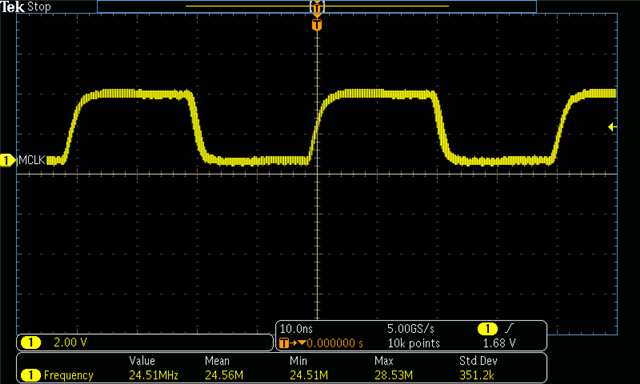
    Please see the following figure which is the master clock at an input sample rate of 96 kHz: 

    Thanks and regards,

    Cherry

  • Hi Cherry, The parts  are tested at ATE and performance has been verified, so it has to be either the layout is causing a problem or the clock jitter or cleanness of power lines. I assume the input signal/file has been verified ( for example it is not clipping or doesn't  have  harmonics of its own).

    They tried 2.2Vrms, , have they checked any other voltage just to get more data point?

    As I mentioned,  sometimes the physical size of the cap or even a wrong polarity of installed cap (if applicable here) can make a difference on the board

    I suggest to compare the design and layout with our reference design in user's guide to make sure there is no major discrepancy. 

    Regards,

    Arash