This thread has been locked.

If you have a related question, please click the "Ask a related question" button in the top right corner. The newly created question will be automatically linked to this question.

TAS5825MEVM: Without audio output after setting.

Part Number: TAS5825MEVM
Other Parts Discussed in Thread: TAS5825M

Hello, I used the PPC3 to control the TAS5825MEVM, but I have some problems here.

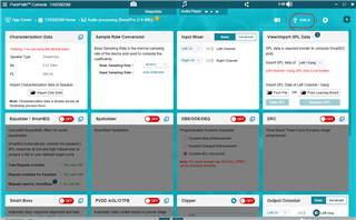
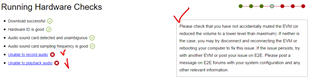
a. During the configuration via PPC3 and running hardware check, there’re two errors that occur as below, may I know what’s going on?

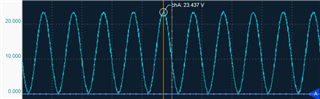
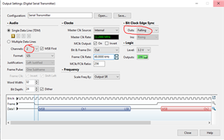
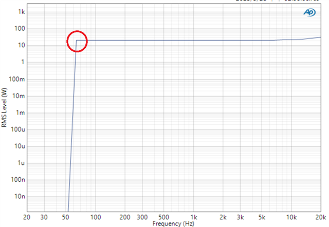
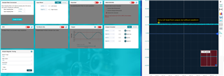
b. After configuring via PPC3, TAS5825M is in the output mode, but when I generate the 1KHz signal from Audio Precision, I cannot get any waveform from TAS5825M output (measure by scope), only 12V level on it.

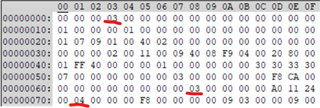
c. After configuring via PPC3, I read the whole register map by my I2C tool, it shows the 0x03=03 (play mode), 0x68=03 (play mode), 0x71=04.

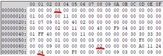
Then I restart the EVM, write the register by my tool, not the PPC3 software, and write the 0x03=02(Hiz mode), then write 0x03=03(play mode), and I got the different register map as below, 0x03=03, 0x68=02(Hiz), 0x71=04.

May I know, what is the correct setting step to set the register then I can into play mode via our tool or MCU?

Sincerely,

Sco

  • Hello, now I can make the EVM work correctly, and get the correct output as below.


    I have only one problem, can I use the I2C Monitor to make the EVM into play mode (not use the APP UI).

    For example, I write the register via I2C Monitor as below:

    w 98 00 00

    w 98 7F 00

    w 98 03 12

    After pressing the execute, I write the 0x03 register as below:

    W 98 03 03 and then Execute.


    Now I got 0x68=02, and 0x71=04, could you tell me, how to set the correct step then I can into play mode?

  • Hi Sco

       Please follow below sequence. 

     1. Connect USB and power up for the EVM.

     2. Use PPC3 connect the board, and goes into Audio processing first, choose correct audio input port as your using, like below picture.

     3. Use oscilloscope check on the LRCLK and SCLK, to see if there's correct clock frequency. If there's no clock, usually means you didn't correct doing on the first two points. Go back and check every thing.

    4. Could continue control, using UI or I2C directly.

  • Hi Shadow He,

    Thanks for your reply, after steps 1 and 2, it works for me, but I still have a question.

    If I would like to use the I2C control directly, for example, from step 1, connect the USB and power up for the EVM, after then, can I use the I2C control for the audio input?

    Because our PCBA is already complete, but I cannot control TAS5825m via MCU directly.

    Sincerely,

    Sco

  • Hi Sco

       You need to finish step 2 to get the correct clock signal on the EVM, and step 3 is to check if every step is going on well. Please finish step 3, then to use I2C script to control. Your major problem for now, is not able to generate clock signal on the board, and will always find 0x68=02 (Hi-Z), 0x71=04 (clock fault).

       If you don't want to use this way, you could consider not using Mother board, only use the small TAS5825M EVM. You need to provide PVDD input, provide DVDD input, also provide LRCLK and SCLK. SCL and SDA also has test point on the board, you could send in signal from these test point.

  • Hi Shadow He,


    Thanks for your reply, I only use the small TAS5825M EVM, then provide the PVDD/DVDD input, and next, connect the LRCLK and SCLK via Audio Precision.


    Using the I2C tool to set the register

    w 98 4C 01

    w 98 03 02


    After I read the register below.

    r 98 68 02

    r 98 71 04


    I check the LRCLK and SCLK via scope, and those pins work correctly, but after I set the register as below

    w 98 03 03


    Then read the register.

    r 98 68 03

    r 98 71 04


    It is already in play mode, then I switch on the audio precision to “on” for the SDIN pin.


    Now I got registers as below.

    r 98 68 02

    r 98 71 04


    I cannot get the 1KHz sine wave from the output, may I know, any other register that I need to set?


    Sincerely,

    Sco

  • Hi Sco

       The AP settings for I2S maybe hard for our device to recognize. Please set as below picture and have try.

  • Hi Shadow He,


    Thanks for your reply, it works for me, but after I test my PCBA frequency response via Audio Precision, it has something wrong around 60Hz as below.


    Then I read the registers as below.


    r 98 61 01

    r 98 71 01


    When I try to set the Audio Precision as below, once I press the "on" button, the error occurs again, without any output, and quit the play mode.


    From the datasheet Table 9-57 GLOBEL_FAULT1, it means PVDD UV fault, may I know, what the PVDD UV fault means?

    Sincerely,

    Sco

  • Hi Sco

    may I know, what the PVDD UV fault means?

    It means PVDD under voltage. Please check if you set any current limit for your power supply. The low frequency will need more peak current.